2
TLP Pro 525M, 725M, and 1025M Series • Setup Guide (Continued)
Mounting
All these touchpanels can be wall-mounted, either using a UL-listed junction box, an external wall box, or directly into drywall or
furniture. Suitable mounting accessories can be found at
www.extron.com
.
ATTENTION:
•
Do not install touchpanels in a fire resistant rated wall or partition assembly.
•
Ne pas installer les écrans tactiles sur un mur protégé par un dispositif coupe-feu ou dans une cloison.
•
All structural steps and electrical installation must be performed by qualified personnel in accordance with local and
national building codes and electrical codes.
•
Toute étape structurelle et installation électrique, doit être effectuée par un personnel qualifié, conformément aux
codes du bâtiment, aux codes incendie et sécurité, et aux codes électriques, locaux et nationaux.
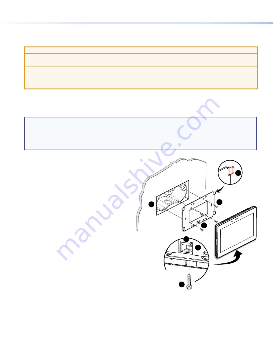
Figure 1 shows the TLP Pro 725M. Installation for the TLP Pro 525M or TLP Pro 1025M is very similar.
With a Wall Box or Junction Box
Some local building codes require the touchpanel to be mounted in a junction box. Junction boxes or wall boxes must be purchased
separately.
NOTES:
•
The TLP Pro 525M touchpanels mount to a 1-gang junction box. The TLP Pro 725M and 1025M touchpanels mount to a
2-gang junction box.
•
Extron provides four 3/4" #6-32 Philips pan head screws for mounting to US junction boxes
•
Extron provides two 16 mm M 3.5 Philips pan head screws for mounting to MK junction boxes
•
EU junction boxes are usually provided with their own screws.
With a wall box
1.
Install a junction box or wall box (see figure 1,
1
),
following the instructions provided by the manufacturer.
2.
Fasten the mounting plate to the wallbox (
2
) with
the provided screws. Use the mounting holes that
are appropriate to the junction box you are using (see
figure 2
, on the following page).
3.
Run and connect cables to the back of the touchpanel
(see
Rear Panel Features
on the following page).
4.
The TLP Pro 525M mounting plate has two hooks
(one in each top corner). The TLP Pro 725 M and
TLP Pro 1025M mounting plate has four hooks (
3
), one
in each corner (see
figure 2
).
Position the touch panel so that the mounting slots (see
figure 4
,
D
) in the rear of the touchpanel align with
these hooks.
5.
Move the touchpanel inward and downward so that
touchpanel sits securely on the hooks and the tongue at
the bottom of the mounting plate (
4
) sits in the groove
in the bottom of the touchpanel (see inset, figure 1,
5
).
6.
Fasten the touchpanel to the mounting plate with the
lock screw (
6
).
steps 3 through 6
TOP
e
Back View
1
2
3
4
5
6
4
Figure 1.
Mounting the TLP Pro 725M with a Junction Box
figure 1


