


2
TLP Pro 1220TG, TLP Pro 1520TG, and TLP Pro 1720TG • Setup Guide
Mounting
A range of optional mounting kits are available for all three models. The
kits must be purchased separately. Follow the installation instructions
provided with the kit.
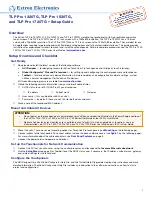
Removing the back and base covers
Some of these procedures require the back and base covers to be
removed. You must remove the back cover before you can remove the
base cover.
1.
Use the provided Extron removal tool. There is one notch on each
side of the back cover (figure 1,
1
). Insert the tool into the notch to
release the catch.
2.
Use the removal tool to remove the base cover. There are two
notches at the back of the base (
2
).
2.
Drill two pilot holes into the desktop.
3.
Remove the base cover (see Removing the Back and Base
Covers, above).
4.
Insert two #10 flat-head wood screws (not provided) through
the touchpanel and align them with the two pilot holes.
5.
Secure the touchpanel to the tabletop.
6.
Replace the base cover.
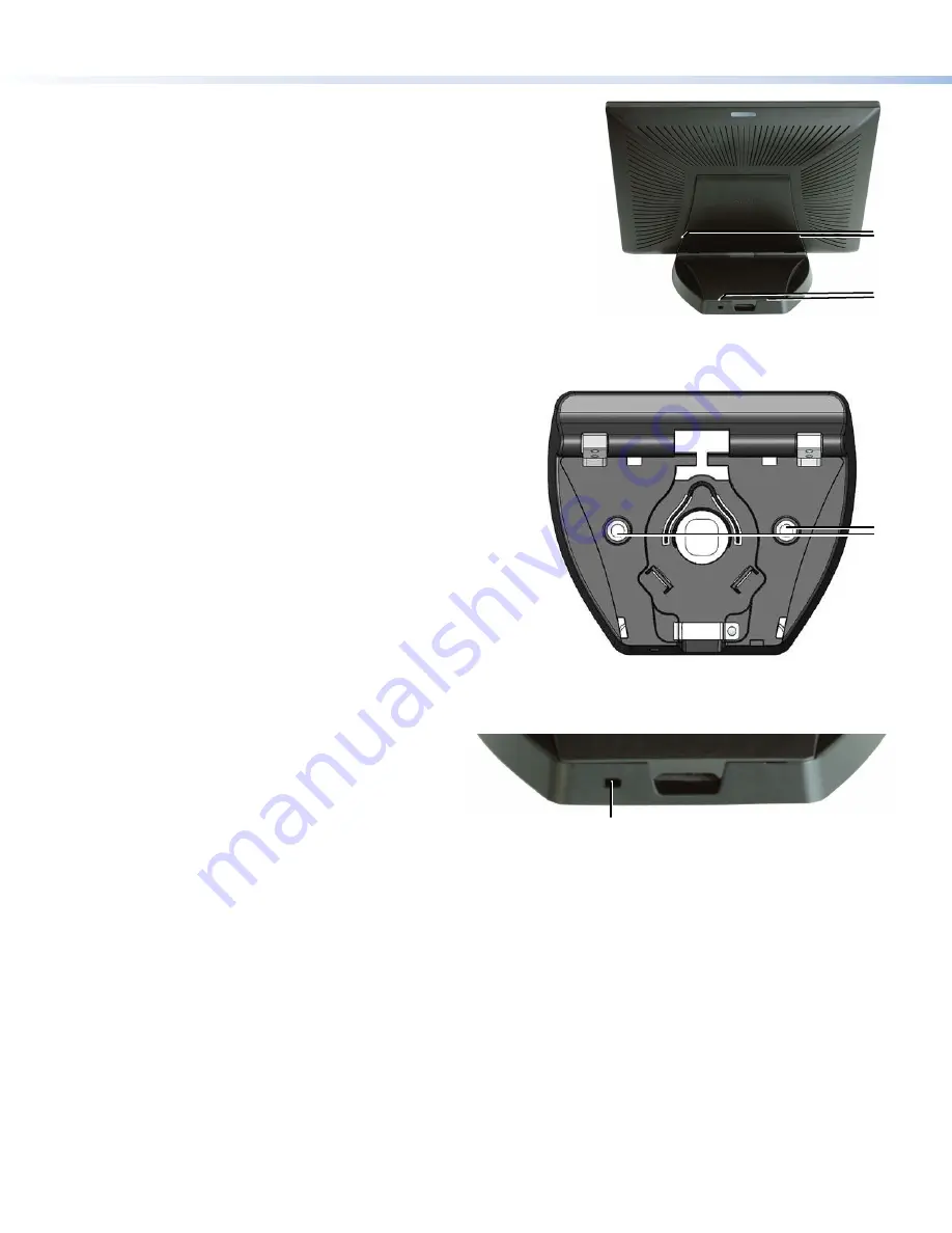
Kensington
®
Security Lock
For added security, attach a Kensington Security Lock
(not provided) to the metal-reinforced Kensington Security
Slot on the rear edge of the base (figure 3,
1
). The figure
shows the rear edge of the TLP Pro 1520TG base, but the
bases of the TLP Pro 1220TG and TLP Pro 1720TG are
very similar. Follow the instructions that are provided by the
manufacturer to install the lock.
Desktop Mounting
The TLP Pro 1220TG, TLP Pro 1520TG, and TLP Pro 1720TG
come assembled with stands that allow the units to be placed on
any suitable flat surface (for example a desk, table, or lectern).
Fixed Mounting
Figure 2 shows the base of the TLP Pro 1220TG, with the cover
removed to indicate the position of the mounting holes. The bases
of the TLP Pro 1520 TG and TLP Pro 1720TG are similar and the
spacing of the mounting holes (figure 2,
1
) is identical.
1.
Mark the location for two holes, 4.96 inches (126 mm) apart.
This measurement is the same for all three models.
1
1
SMA-1 Swivel Mount Adapter
To swivel either device up to 180° in either direction, use the optional Extron SMA-1 swivel mount adapter, to permanently mount the
touchpanels.
1.
Remove the back cover and base cover (see
Removing the back and base covers
2.
Attach the conduit, insulation disk, and swivel disk and configure the set screws to allow for the degree of swivel that is required
(see the
SMA-1 Swivel Mount Adapter Kit User Guide
).Place the mounting hole in the base over
the conduit of the SMA-1.
3.
Secure the unit with the backing plate and locking nut as described in the
SMA-1 Swivel Mount Adapter Kit User Guide
.
VESA Mounting
Use a third-party D-type VESA mounting kit with the 100 mm x 100 mm mounting pattern.
1.
Remove the back cover.
2.
Remove the four screws holding the touchpanel to the base. There are two screws in each base attachment hinge
(
K
on page 4).
3.
Follow the instructions provided with the VESA mounting kit.
1
1
1
1
2
2
Figure 1.
Remove the Back and Base Covers
Figure 2.
Mounting Holes in TLP Pro 1220TG Base
Figure 3.
Slot for Kensington Security Lock


