background image

2-11

QSD 204 • Installation and Operation

Input 1 can only input composite video, and Input 3 can only input S-video,
no other video types are selectable for these inputs.  Only inputs 2 and 4
offer selectable video types.  From the Input Configuration menu, pressing
the Next key repeatedly will display submenus with the input video types
for Inputs 2 and 4.  The SDI input (if any) can be assigned to any input from
the Input Configuration submenus.

Input 2 Video Type

Rotate either the Adjust horizontal 

(

)

 knob  or Adjust vertical 

( )

 knob while in

the Input 2 submenu to select the appropriate video format (composite, S-video,
component) for input 2.  The default is component video.

Input 4 Video Type

Rotate the Adjust horizontal 

(

)

 knob while in the Input 4 submenu to select the

appropriate video format (RGBS, RGBcvS) for input 4.  The default is RGBS.

SDI input (SDI IN)

Rotate either the Adjust horizontal 

(

)

 knob  or Adjust vertical 

( )

 knob while in

the SDI Input submenu to select the input # for the SDI input.  The SDI input can
be assigned to inputs 1, 2, 3, 4, or none (*).  The default is none.

After the SDI input is no longer assigned to an input, either because it has
been assigned to a new input or is set to none, the input reverts back to the
last video type that was assigned to it.

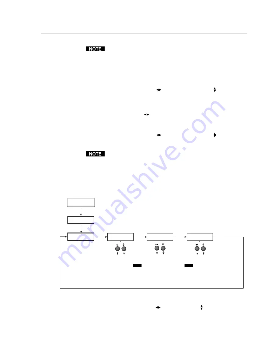
Output Configuration

The following flowchart provides an overview of the Output Configuration
submenus and the options for each setting.

Output Signal (Signal)

Using either the Adjust horizontal 

(

)

 or Adjust vertical 

(

) knob, select the

output video format required by the display: RGB (default), YUV,  or RGsB.

Sync Polarity (H Sync V)

The display or projector may require a particular combination of horizontal (H)
and vertical (V) sync signal polarities.  Select the appropriate combination of

Extron

QSD204D

OUTPUT

CONFIG

MENU

NEXT

SIGNAL

RGB

H SYNC V

NEG          POS

NEXT

NEXT

NEXT

INPUT

CONFIG

MENU

Output video types
•  RGB (default)
•  YUV
•  RGsB

Sync polarity combinations
•  H-/V- (default)
•  H-/V+

•  H+/V-
•  H+/V+


NOTE

    This submenu is only active for RGB.

    If the signal type was specified as

                RGsB or YUV in the previous submenu,
                the sync polarity submenu will not display.

SERRATION

<OFF>       ON

Serration pulse removal
•  Off (default)
•  On

NOTE

      When set on, serration pulses are

    removed from the output vertical sync
    pulse.  LCD, DLPs, and plasma displays
    must have the serration pulses removed
    from the sync signal in order to display
    properly.  Flagging or bending at the top of the
    video image is a sign that the serration pulses
    should be removed.

Содержание QSD 204

Страница 1: ...QSD 204 Quad Standard Decoder series QSD 204 and QSD 204 D 68 651 01 Printed in the USA...

Страница 2: ...uipos Este s mbolo se utiliza para advertir al usuario sobre la presencia de elementos con voltaje peligroso sin protecci n aislante que puedan encontrarse dentro de la caja o alojamiento del producto...

Страница 3: ...is the same for both outputs Video Camera DVD Player INPUTS R Y 50 60 Hz 1 2 3 4 Y VID B Y C H R R Y V G Y S B B Y VIDEO REMOTE RGB R Y Y B Y RGBS RGBcvs S VIDEO SDI OUTPUTS 100 240V 0 3A QSD 204 VCR...

Страница 4: ...here is no signal present at the currently selected input connector 1 2 3 4 EXTRON QSD204D INPUT CONFIG MENU NEXT INPUT 2 COMPNENT INPUT 4 RGBcvS SDI IN 1 2 3 4 NEXT NEXT NEXT Input 2 video types Comp...

Страница 5: ...rtical sync pulse LCD DLPs and plasma displays must have the serration pulses removed from the sync signal in order to display properly Flagging or bending at the top of the video image is a sign that...

Страница 6: ...ly occurs if there is no signal present at the currently selected input connector EXTRON QSD204D 2 sec 2 sec INPUT 1 CMPOSITE 2 sec NO SIGNAL 2 sec The No Signal default menu only occurs if there is n...

Страница 7: ...ttons 2 7 Picture adjustment buttons 2 7 Menu button 2 8 Next button 2 8 LCD menu display and controls 2 8 Menus Configuration and Adjustments 2 9 Moving through menus by using front panel controls 2...

Страница 8: ...2 Using the command response tables 3 3 Command response table for SIS commands 3 4 Command response table for special function SIS commands 3 7 Control Software for Windows 3 8 Installing the softwar...

Страница 9: ...QSD 204 1 Chapter One Introduction About this Manual About the QSD 204 Features and Options...

Страница 10: ...mote control which has most of the front panel controls Features and Options Features Quad standard decoder The QSD 204 converts interlaced S video and composite video signals following either the NTS...

Страница 11: ...ing portion of a signal by using this feature RS 232 configuration The QSD 204 can be configured by using the Extron control software for Windows or by using a third party control system Versatile mou...

Страница 12: ...Introduction cont d QSD 204 Introduction 1 4...

Страница 13: ...allation and Operation Mounting the Decoder Rear Panel Features Front Panel Features Menus Configuration and Adjustments Image Adjustments Input Reset System Reset Executive Mode IR 901 Infrared Remot...

Страница 14: ...rack shelf with the two provided 4 40 x 1 8 machine screws Insert the screws from the underside of the shelf and securely fasten them into diagonally opposite corners See the illustration below Rack m...

Страница 15: ...surface 3 Drill 3 32 2 mm diameter pilot holes 1 4 6 3 mm deep into the marked bracket screw holes on the furniture mounting surface 4 Insert the four 8 wood screws into the four pilot holes Tighten...

Страница 16: ...standard IEC power cord into this connector to connect the decoder to a 100 to 240VAC 50 Hz or 60 Hz power source The front panel control and input selection LEDs will light during power up 2 Video in...

Страница 17: ...terface input connector Connect an SDI signal to this female BNC connector SDI Only the QSD 204 D model has an SDI connector 6 Video input 4 RGBS or RGBcvS Connect an RGBS or RGBcvS video signal to th...

Страница 18: ...ud 1 stop bit no parity and no flow control The rear panel RS 232 9 pin D female connector has the following pin assignments Pin RS 232 function Description 1 Input 1 Contact closure 2 Tx Transmit dat...

Страница 19: ...s Pressing these buttons successively will toggle between the different picture adjustment functions and light the LEDs above and below each button 5 Color Tint control button Col Tnt This button cont...

Страница 20: ...QSD 204 See the Menus Configuration and Adjustments section in this chapter for details Next button 8 Next button Use this button to step through the submenus in the QSD 204 menu system See the Menus...

Страница 21: ...stments Image adjustment buttons Col Tnt color tint Brt Cont brightness contrast Center and Blanking When one of these buttons is pressed repeatedly the corresponding image adjustment menu appears on...

Страница 22: ...04D INPUT CONFIG MENU NEXT INPUT 2 COMPNENT INPUT 4 RGBcvS SDI IN 1 2 3 4 NEXT NEXT NEXT Input 2 video types Composite S video Component default Assign SDI to Input 1 2 3 4 none Input 4 video types RG...

Страница 23: ...r because it has been assigned to a new input or is set to none the input reverts back to the last video type that was assigned to it Output Configuration The following flowchart provides an overview...

Страница 24: ...nfiguration submenus and the options for each setting Detail control This submenu allows adjustment of the image detail sharpness of the output display The adjustment ranges from 0 to 63 The default i...

Страница 25: ...Adjust horizontal or Adjust vertical knob to specify this mode as On or Off The default is Off The Autoswitch mode ignores the presence of an SDI input signal so any input which is assigned an active...

Страница 26: ...color tint brightness contrast centering or blanking follow the steps below An example of making color adjustments shown in the flowchart below demonstrates the process which is similar for all the o...

Страница 27: ...QSD 204 s front panel but not the IR 901 is affected by Executive mode The IR 901 will still be able to control the decoder after Executive mode has been enabled When Executive mode is active all fun...

Страница 28: ...r input selection buttons 1 2 3 4 Inputs 5 and 6 and the Take button are not functional The middle portion of the IR 901 features the size and centering buttons The bottom part contains the adjustment...

Страница 29: ...ult from using long cables or from improper termination A sync adapter such as Extron s ASTA active sync termination adapter may help solve these problems 6 For LCD and DLP projectors and plasma displ...

Страница 30: ...Installation and Operation cont d QSD 204 Installation and Operation 2 18...

Страница 31: ...QSD 204 3 Chapter Three Serial Communication RS 232 Programmer s Guide Control Software for Windows...

Страница 32: ...with a carriage return and a line feed CR LF which signals the end of the response character string A string is one or more characters Decoder initiated messages When a local event such as a front pan...

Страница 33: ...carriage return line feed hex 0D 0A Space Esc Escape key X1 Specific input number 0 through 4 0 no input 1 input 1 2 input 2 and so forth X2 0 off 1 on X4 Video signal type 1 through 7 1 composite vid...

Страница 34: ...al type X5 X5 Typ X4 Show the video signal type Example 2 2Typ3 Example show input 2 video type 3 YUV Color Set a specific color value X10 C Col X10 Specify a color adjustment level Example 47C Col047...

Страница 35: ...ue Blt X17 Increase the of top lines blanked Decrease the top blanking value Blt X17 Decrease the of top lines blanked View the top blanking value Blt X17 Show the number of lines that are blanked at...

Страница 36: ...roller firmware version Request part number N N60 501 0_ Show the decoder s part Request general info I See below Show the decoder s status C X1 Typ X4 Std X12 Sdi X1 Zap reset to default settings Zap...

Страница 37: ...nable enhanced mode Decoder settings Output signal 6 X Syn X 0 RGB 1 YUV 2 RGsB sync on green SOG Example 6 0 Syn0 Example RGB sync output Decoder output polarity 7 X Pol X 0 H V default 1 H V 2 H V 3...

Страница 38: ...UP EXE from the floppy disk 2 Follow the instructions that appear on the screen By default the installation creates a C QSD 204 directory and it places two icons QSD 204 Control Pgm and QSD 204 Help i...

Страница 39: ...mputer key or click on the Help menu from within the QSD 204 Control Program or double click on the QSD 204 Help icon in the Extron Electronics group or folder For explanations of buttons or functions...

Страница 40: ...Serial Communication cont d QSD 204 Serial Communication 3 10...

Страница 41: ...QSD 204 A Appendix Appendix Specifications Part Numbers and Accessories Firmware Upgrade Installation Serial Digital Interface SDI Card Installation...

Страница 42: ...BS RGsB or component video Connectors 6 BNC female 1 15 pin HD female Minimum maximum levels 0 0V to 0 7V p p Impedance 75 ohms Vertical frequency 50 Hz to 60 Hz Sync Input type RGBS RGBcvS Output typ...

Страница 43: ...Rack mount Yes with optional rack shelf part 60 190 01 Enclosure type Metal Enclosure dimensions 1 75 H x 8 75 W x 9 5 D 1U high half rack width 4 4 cm H x 22 2 cm W x 24 1 cm D Depth excludes connect...

Страница 44: ...et self adhesive 4 25 020 02 IEC power cord 27 044 01 Tweeker small screwdriver 100 014 01 QSD 204 User s Manual 68 651 01 DVS 406 Windows based control program 29 017 01 QSD 204 label 33 718 01 Acces...

Страница 45: ...hock or damage always unplug the QSD 204 decoder from the AC power source before opening the enclosure 2 Remove the decoder from the rack or furniture 3 Remove the cover of the decoder the top half of...

Страница 46: ...ocated in opposite ends of the U41 firmware chip 6 Insert the hooks into the slots and squeeze the tool gently to grasp the chip 7 Pull the chip straight out of the socket and set it aside 8 Align the...

Страница 47: ...e decoder the top half of the enclosure by removing the screws then lifting the cover straight up See the top cover removal diagram in the Firmware Upgrade Installation section Do not touch any switch...

Страница 48: ...n the SDI card should now be directly over the standoff 7 Insert the card s installation screw through the SDI card s mounting hole and gently tighten it into the standoff 8 Install the SDI connector...

Отзывы: