background image


6-19

MVX Plus 128 VGA A Matrix Switcher • HTML Operation

PRELIMINAR

Y

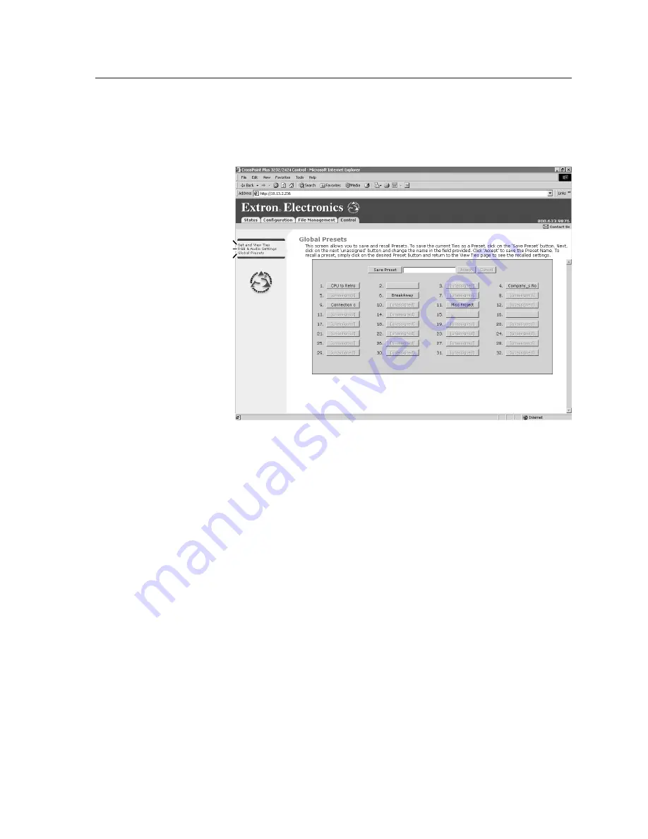
Global Presets page

You can save and recall global presets from the Global presets page (figure 6-20).  

Access the Global presets page by clicking the 

Global Presets

 link on the left of the 

Control page.

Select RGB & Audio Settings.

Refresh.

Select Set & View Ties.

Figure 6-20

 —

 Global Presets page

Saving a preset

Save the current configuration (configuration 0) as a preset as follows:

1

Click the 

Save Preset

 button.

2

Select the desired preset by clicking on one of the presets listed.  To create a 

new preset, click one of the 

[unassigned]

 buttons.  Overwrite an existing 

preset by clicking an already existing preset.

3

If desired, type over the current name in the box adjacent to the 

Save Preset


button.

N

  Preset names are limited to 12 upper and lower case alphanumeric characters 

and the  {space}  _  and  /  characters.

N

  The following characters are invalid in preset names: 

+  ~  ,  @  =  ‘  [  ]  {  }  <  >  ’  “  ;  :  |  \  and ?.


If you do not rename an unassigned button, the MVX Plus 128 VGA A 

switcher names the preset as Preset {next available number}.


If you do not rename an existing preset when it is overwritten, the 

MVX Plus 128 VGA A switcher retains the same name.

4

Click the 

Accept

 button.

Recalling a preset

To recall a global preset to be the current configuration, click the button associated 

with the desired preset.

Содержание MVX Plus 128 VGA A

Страница 1: ...MVX Plus 128 VGA A Computer video VGA and Audio Matrix Switcher 68 521 30 Rev B 04 07 ...

Страница 2: ...al verwenden sollten Sie alle Sicherheits und Bedienungsanleitungen genau durchlesen und verstehen Aufbewahren der Anleitungen Die Hinweise zur elektrischen Sicherheit des Produktes sollten Sie aufbewahren damit Sie im Bedarfsfall darauf zurückgreifen können Befolgen der Warnhinweise Befolgen Sie alle Warnhinweise und Anleitungen auf dem Gerät oder in der Benutzerdokumentation Keine Zusatzgeräte V...

Страница 3: ...anual may cause harmful interference to radio communications Operation of this equipment in a residential area is likely to cause harmful interference in which case the user will be required to correct the interference at his own expense N Thisunitwastestedwithshieldedcablesontheperipheraldevices Shielded cables must be used with the unit to ensure compliance This device complies with Part 15 of t...

Страница 4: ......

Страница 5: ...ion also called configuration 0 Global preset A configuration that has been stored One global preset can be assigned to each input button When a global preset is retrieved from memory it becomes the current configuration Front Panel Controls Input and output buttons select inputs and outputs Output buttons light amber to indicate video and audio ties The buttons light green to indicate video only ...

Страница 6: ...ndicates audio only tie Green indicates the need to confirm the change PRESET PRESET PRESET PRESET Preset button blinks Press and hold 2 seconds Save a preset Recall a preset Preset button lights Press and release All input and output buttons with assigned presets light red The configuration data at assigned preset locations will be overwritten INPUTS 1 2 3 4 5 6 7 1 ENTER The button blinks red to...

Страница 7: ... Indicators 3 2 Definitions 3 2 Input and output buttons 3 3 Control buttons 3 4 I O controls 3 7 Button icons 3 8 Front Panel Operations 3 8 Front panel security lockouts 3 8 Power 3 8 Creating a configuration 3 9 Example 1 Creating a set of video and audio ties 3 10 Example 2 Adding a tie to a set of video and audio ties 3 12 Example 3 Removing a tie from a set of video and audio ties 3 14 Viewi...

Страница 8: ...perations 3 44 Performing soft system resets 3 45 Performing a hard reset 3 46 Optimizing the Audio 3 47 Troubleshooting 3 47 Configuration Worksheets 3 48 Worksheet example 1 System equipment 3 48 Worksheet example 2 Daily configuration 3 49 Worksheet example 3 Test configuration 3 50 Configuration worksheet 3 51 Chapter Four Programmer s Guide 4 1 Serial Ports 4 2 Rear panel Remote port 4 2 Fron...

Страница 9: ... local field 5 9 Sync Time to PC button 5 9 GMT offs et field 5 9 Use Daylight Savings checkbox 5 10 Administrator Pas s word field 5 10 User Pas s word field 5 10 Mail Server IP Addres s field 5 11 Mail Server Domain Name field 5 11 E mail Addres s ee fields 5 12 Updating firmware 5 13 Ethernet connected firmware upload 5 14 Serial port connected firmware upload 5 15 Uploading HTML files 5 17 Win...

Страница 10: ...ware field 6 6 Model field 6 6 Part Number field 6 7 Date Time Settings fields 6 7 Passwords page 6 8 Email Settings page 6 9 Mail IP Addres s field 6 9 Domain Name field 6 9 Email addres s fields 6 10 Firmware Upgrade page 6 10 File Management Page 6 11 Set and View Ties Page 6 12 Creating a tie 6 13 RGB and Audio Settings page 6 13 Changing the input gain and attenuation 6 14 Muting and unmuting...

Страница 11: ...er and Esc key A 5 Local echo A 5 Set carriage return line feed A 5 Close A 5 Help A 5 Quit A 5 Subnetting A Primer A 6 Gateways A 6 Local and remote devices A 6 IP addresses and octets A 6 Subnet masks and octets A 6 Determining whether devices are on the s ame subnet A 7 Appendix B Specifications Part Numbers Accessories B 1 Specifications B 2 Part Numbers and Accessories B 5 Included parts B 5 ...

Страница 12: ...Table of Contents cont d MVX Plus 128 VGA A Matrix Switcher Table of Contents vi PRELIMINARY 68 521 30 B 04 07 All trademarks mentioned in this manual are the properties of their respective owners ...

Страница 13: ...PRELIMINARY MVX Plus 128 VGA A Matrix Switcher 1 Chapter One Introduction About this Manual About the MVX Plus 128 VGA A Matrix Switcher Definitions Features ...

Страница 14: ... and any input s can be switched to any one or all outputs with virtually no crosstalk or signal noise between channels INPUTS OUTP UTS RESET RS232 RS422 REMOTE LIS TE D 1T2 3 I T E C US 1 2 3 4 5 6 7 8 9 10 11 12 LAN 1 2 3 4 5 6 7 8 1 2 3 4 5 6 7 8 9 10 11 12 1 2 3 4 5 6 7 8 INPUTS OUTP UTS Control System Plasma Plasma LCD Projector VSC 500 SCAN CON VERT ER SIZE MIN MAX NEX T MEN U FREE ZE RES ET...

Страница 15: ...m A control system A PC An Extron MKP 2000 remote control panel An Extron MKP 3000 remote control panel An Extron MCP 1000 remote control panel and or MKP 1000 remote keypad The matrix switcher is housed in a rack mountable 2U high metal enclosure with mounting flanges for a standard 19 rack The appropriate rack mounting kit is included with the switcher The switchers have an internal 100 VAC to 2...

Страница 16: ...a the switchers serial port or LAN port The frequency information can be displayed on any control system or in a Windows based control program on a local area network LAN or Internet IP connection figure 1 2 OR Input Horz Vert 01 31 50 60 00 02 31 50 60 00 03 31 50 60 00 04 48 01 67 50 05 48 01 67 50 06 48 01 67 50 07 48 01 67 50 08 61 55 72 00 09 61 55 72 00 10 61 55 72 00 11 61 55 72 00 12 61 55...

Страница 17: ...delay and audio gain and attenuation and volume control audio models The front panel features illuminated pushbuttons that can be labeled with text or graphics Windows based control program For Ethernet or serial port remote control from a PC the Extron Windows based control software provides a graphical interface and drag and drop point and click operation The Windows based control program also h...

Страница 18: ...open area where operation by unauthorized personnel may be a problem either of two security lockout modes can be implemented the third mode is unlocked When a front panel locked mode is enabled a special button combination or SIS command is required to unlock the front panel controller and make the front panel fully operational I O grouping This feature allows the matrix to be virtually divided in...

Страница 19: ...PRELIMINARY MVX Plus 128 VGA A Matrix Switcher 2 Chapter Two Installation Mounting the Switcher Rear Panel Cabling and Views Front Panel Configuration Port ...

Страница 20: ...oading Mount the equipment in the rack so that a hazardous condition is not achieved due to uneven mechanical loading 4 Circuit overloading Connect the equipment to the supply circuit and consider the effect that circuit overloading might have on overcurrent protection and supply wiring Appropriate consideration of equipment nameplate ratings should be used when addressing this concern 5 Reliable ...

Страница 21: ...onnections Video connections N The switcher does not alter the video signal in any way The signal output by the switcher is in the same format as the input N The MVX Plus 128 switcher can also switch RGBS RGsB RsGsBs component video S video or composite video by using the appropriate adapters a RGB video inputs Connect the analog computer video sources to these 15 pin HD female connectors N Most l...

Страница 22: ...r audio inputs C The length of the exposed stripped portion of the copper wires is important The ideal length is 3 16 5 mm Longer bare wires can short together Shorter bare wires are not as secure in the direct insertion connectors and could be pulled out C The captive screw audio connector can easily be inadvertently plugged partially into one receptacle and partially into an adjacent receptacle ...

Страница 23: ... s Guide chapter 5 Matrix Software and chapter 6 HTML Operation for details RS 232 RS 422 connection e RS 232 RS 422 connector Connect a host device such as a computer touch panel control or RS 232 capable PDA to the switcher via this 9 pin D connector for serial RS 232 RS 422 control figure 2 5 RS 232 Function Pin Function 1 2 3 4 5 6 7 8 9 TX RX Gnd Not used Transmit data Receive data Not used S...

Страница 24: ... the correct cable type and that they be properly terminated with the correct pinout Ethernet links use Category CAT 5e or CAT 6 unshielded twisted pair UTP or shielded twisted pair STP cables terminated with RJ 45 connectors Ethernet cables are limited to a length of 328 100 m N Do not use standard telephone cables Telephone cables do not support Ethernet or Fast Ethernet Do not stretch or bend c...

Страница 25: ...tcher For two different reset levels press and hold the button while the switcher is running or while you power up the switcher See Rear Panel Controls in chapter 3 Operation for details Events mode 3 reset Hold Reset for 3 seconds then release it and push it again to toggle events monitoring on and off IP settings mode 4 reset Hold Reset for 6 seconds then release it and push it again to reset th...

Страница 26: ...RS 232 cable N This port is independent of the rear panel Remote port and is not affected by changes to the rear panel port s protocol This front panel port s protocol can be changed under SIS command control only See the Command Response table for IP SIS commands in chapter 4 Programmer s Guide to configure all ports under SIS control N A front panel Configuration port connection and a rear panel...

Страница 27: ...NARY MVX Plus 128 VGA A Matrix Switcher 3 Chapter Three Operation Front Panel Controls and Indicators Front Panel Operations Rear Panel Operations Optimizing the Audio Troubleshooting Configuration Worksheets ...

Страница 28: ... switchers are used throughout this manual Tie An input to output connection Set of ties An input tied to two or more outputs An output can never be tied to more than one input Configuration One or more ties or one or more sets of ties Current configuration The configuration that is currently active in the switcher also called configuration 0 Global memory preset A configuration that has been stor...

Страница 29: ...el See Viewing and adjusting the output volume on page 3 36 Input 1 and Input 2 only Toggle background illumination of the buttons on and off See Background illumination on page 3 43 b Output buttons The output buttons have two primary functions and four secondary functions Select output s Identify the selected output s Output 1 only With the Input 1 button select I O Group mode See I O grouping o...

Страница 30: ...at the RS 232 RS 422 port is set to 9600 baud in Serial Port Configuration mode See Selecting the rear panel Remote port protocol and baud rate on page 3 43 With the RGBHV and Audio buttons select front panel security Lock mode 2 or toggle between mode 0 unlocked and mode 2 See Setting the front panel locks Executive modes on page 3 41 d Preset button The Preset button has two primary functions an...

Страница 31: ... of switches to the selected output See Setting RGB delay on page 3 23 Decrease the audio level of the selected input See Viewing and adjusting the input audio level on page 3 32 Decrease the volume of the selected output See Viewing and adjusting the output volume on page 3 36 With the Enter Preset and Esc buttons select Serial Port Configuration mode See Selecting the rear panel Remote port prot...

Страница 32: ...ee I O grouping on page 3 19 Increase the RGB delay of switches to the selected output See Setting RGB delay on page 3 23 Increase the audio level of the selected input See Viewing and adjusting the input audio level on page 3 32 Increase the volume of the selected output See Viewing and adjusting the output volume on page 3 36 With the Enter Preset and View buttons select Serial Port Configuratio...

Страница 33: ...2 RS 422 port is set to the RS 232 protocol in Serial Port Configuration mode See Selecting the rear panel Remote port protocol and baud rate on page 3 43 h Audio button The Audio button has two primary functions and six secondary functions Selects and deselects audio for a configuration that is being created or viewed Lights to indicate that audio is available for configuration or viewing Selects...

Страница 34: ...viewing and adjusting the audio level viewing and adjusting the output volume locking out the front panel performing one of several resets toggling background illumination on and off and reading and setting the RS 232 RS 422 Remote port settings Front panel security lockouts In the procedural descriptions that follow it is assumed that the switcher is in Lock mode 0 fully unlocked The following tw...

Страница 35: ...o clear unwanted outputs press and release the associated lit output buttons To indicate potential unties output buttons blink the appropriate color when an output is deselected but not untied from the input 4 Press and release the Enter button to accept the tie 5 Repeat steps 1 through 4 to create or clear additional ties until the desired configuration is complete N Only one video input and one ...

Страница 36: ...off The button lights green when selected Press the Audio button to toggle on and off The button lights red when selected Figure 3 4 Select RGBHV and audio 3 Press and release the input 5 button figure 3 5 INPUTS 1 2 3 4 5 6 7 8 9 Press and release the Input 5 button The button lights amber to indicate that RGBHV and audio outputs can be tied to this input Figure 3 5 Select an input 4 Press and re...

Страница 37: ...nation Press the Enter button to confirm the configuration change The Enter button returns to unlit or background illumination Figure 3 7 Press the Enter button The current configuration figure 3 8 is now Input 5 video and audio is tied to output 3 output 4 and output 8 Input 5 video audio tied to outputs 3 4 and 8 Input Output 3 4 8 5 Video Audio Figure 3 8 Example 1 final configuration ...

Страница 38: ...he button lights green when selected Press the Audio button to toggle on and off The button is unlit or background illuminated when deselected Figure 3 10 Select RGBHV only 3 Press and release the input 5 button figure 3 11 INPUTS 1 2 3 4 5 6 7 8 9 OUTPUTS 1 2 3 4 5 6 7 8 Press and release the Input 5 button The button lights green to indicate that RGBHV outputs can be tied to or untied from this ...

Страница 39: ...nfiguration change The Enter button returns to unlit or background illumination Figure 3 13 Press the Enter button The current configuration figure 3 14 is now Input 5 video is tied to output 1 output 3 output 4 and output 8 Input 5 audio is tied to output 3 output 4 and output 8 Input 5 video tied to outputs 1 3 4 and 8 Input 5 audio tied to outputs 3 4 and 8 Input Output 1 3 4 8 5 Video Audio Fi...

Страница 40: ...round illuminated when deselected Press the Audio button to toggle on and off The button lights red when selected Figure 3 16 Select audio only 3 Press and release the input 5 button figure 3 17 INPUTS 1 2 3 4 5 6 7 8 9 OUTPUTS 1 2 3 4 5 6 7 8 Press and release the Input 5 button The button lights red to indicate that audio outputs can be tied to and untied from this input The Output 3 Output 4 an...

Страница 41: ...ion change The Enter button returns to unlit or background illumination Figure 3 19 Press the Enter button The current configuration figure 3 20 is now Video Input 5 video is tied to output 1 output 3 output 4 and output 8 Audio Input 5 audio is tied to output 3 and output 8 Input 5 video tied to outputs 1 3 4 and 8 Input 5 audio tied to outputs 3 and 8 Input Output 1 3 4 8 5 Video Audio Figure 3 ...

Страница 42: ...n 4 Select the desired input or output s whose ties you wish to view by pressing the input and output buttons N When you enter View only mode the output buttons light for all outputs without ties Likewise when you press an output button for which there are no ties the output buttons light for all outputs without ties To see all ties of the current configuration press and release each input and out...

Страница 43: ...1 2 3 4 5 6 7 8 OUTPUTS Until you select an input the buttons for all untied outputs light amber if no inputs are tied green if no video inputs are tied only audio is tied or red if no audio inputs are tied only video is tied Press the Audio button to toggle on and off The button lights red when selected Press the RGBHV Video button to toggle on and off The button lights green when selected Red Am...

Страница 44: ...ct RGBHV to view audio ties only 6 Press and release the RGBHV button and the Audio button to toggle the RGBHV button on green and the Audio button either unlit or providing background illumination figure 3 25 I O VIDEO AUDIO OUTPUTS 1 2 3 4 5 6 7 8 Green Green Green Green The output buttons for outputs that are not tied to input 5 are either unlit or background illuminated The output buttons for ...

Страница 45: ...es for operational security reasons VSC 700 SCAN CONVERTER SIZE MIN MAX NEXT MENU FREEZE RESET IR CENTER PAN SIZE USP 405 UNIVERSAL SIGNAL PROCESSOR ADJUST MENU NEXT FREEZE 1 2 3 4 5 PICTURE ADJUSTMENTS CENTER SIZE BRT CONT COL TNT ZOOM DETAIL INPUTS RGB UNIVERSAL FREEZE COMPOSITE S VIDEO SDI INPUTS 1 2 3 4 5 6 7 8 9 10 11 OUTPUTS 1 2 3 4 5 6 7 8 4 input 2 output composite video matrix Camera 1 Ca...

Страница 46: ...ated under RS 232 RS 422 or Ethernet control that tie inputs and outputs across group boundaries These presets are selectable from the front panel An input or output can be assigned to only one group If you assign an input or output to a group and that input or output is already assigned to a different group the older grouping is discarded in favor of the new grouping You can break audio away from...

Страница 47: ... buttons figure 3 29 1 1 1 2 3 3 1 2 3 Press and hold the Input 1 button and Output 1 button Release the Input 1 button and Output 1 button Ungrouped input and output buttons light 2 seconds Figure 3 29 Select I O Group mode 3 Press and release the Enter button to select group 1 figure 3 30 C O N T R O L PRESET ENTER ESC VIEW Press and release the Enter button to select group 1 The button lights a...

Страница 48: ... 2 The button lights amber to indicate the selection 1 3 2 4 Group Figure 3 32 Select an I O group 6 Press and release the input 5 through 8 and output 5 through 8 buttons figure 3 33 INPUTS 1 2 3 4 5 6 7 8 9 OUTPUTS 1 2 3 4 5 6 7 8 Press and release the Input 5 through Input 8 buttons The selected buttons light Press and release the Output 5 through Output 8 buttons The selected buttons light Fig...

Страница 49: ...nel lock mode 2 is selected You can view the delay in lock mode 2 but you cannot change it from the front panel 1 Press the Esc button to clear any input buttons output buttons or control buttons that may be lit 2 To enter RGB Delay mode press and hold the RGBHV button until the button begins to blink green then release the button 3 Press and release an output button to select an output Each lit i...

Страница 50: ...conds Blinking button Figure 3 35 Select RGB Delay mode 3 Press and release the output 17 button figure 3 36 3 1 2 3 INPUTS 1 2 3 4 5 6 9 10 7 8 1 Press and release the Output 1 button The button lights green The Input 1 through Input 10 buttons display the selected output s RGB delay Each lit input button indicates half a second of delay In this example the green input buttons display 3 5 seconds...

Страница 51: ... button to increase the RGB interval that is applied to switches to the selected output by a half second per button push Unlit button Lit button The Input 1 through Input 10 buttons display the selected output s RGB delay Each lit input button indicates half a second of delay In this example the green input buttons display 5 0 seconds of RGB interval Figure 3 37 Adjust the RGB delay interval 5 Pre...

Страница 52: ...ll presets are stored in non volatile memory When power is removed and restored the current configuration is still active and all presets are retained When a preset is recalled it replaces the current configuration which is lost unless it is also stored as a preset The recalled preset overwrites all of the current configuration ties in favor of the preset configuration ties Preset numbers that are...

Страница 53: ...on data at that preset location will be overwritten Red Preset Assigned Unlit No Preset Assigned Figure 3 41 Enter Save Preset mode 3 Press and release the input or output button for the desired preset figure 3 42 C O N T R O L PRESET ENTER ESC VIEW INPUTS 1 2 3 4 5 6 7 8 9 The Enter button blinks to indicate the need to save the preset The Preset button continues to blink Blinking button Press an...

Страница 54: ...r Recall Preset mode 3 Press and release the input or output button for the desired preset figure 3 46 C O N T R O L PRESET ENTER ESC VIEW INPUTS 1 2 3 4 5 6 7 8 9 Press and release the Input 1 button The button blinks red to indicate that this preset number is selected but not recalled The Enter button blinks to indicate the need to recall the preset Blinking button Figure 3 46 Select the preset ...

Страница 55: ...ous state to indicate the unmute 5 Press and release the View button to return to normal switcher operation N You can mute video and audio video only or audio only outputs Pressing and releasing the RGBHV button and the Audio button toggles each selection on and off When you enter View only mode the output LEDs turn on for all outputs without ties The video mute function mutes the R G and B planes...

Страница 56: ...cannot change them from the front panel If front panel Lock mode 2 is selected and you try to perform steps 4 and 5 the actions are ignored 4 One at a time press and hold the Output 3 button and then the Output 4 button figure 3 50 for approximately 2 seconds until each button begins to blink The output 3 and output 4 video and audio signals are muted 3 4 3 4 Press and hold the Output 3 button The...

Страница 57: ... not muted RGBHV only because only video is tied to output 4 Mute outputs one at a time Blinking button 2 seconds 2 seconds Figure 3 51 Unmute the outputs N If both RGBHV and audio are selected the unmuting action toggles both the video and the audio outputs If either the video output or the audio output is already unmuted the muted output is unmuted and the unmuted output is muted 6 Press and rel...

Страница 58: ...o clear any input buttons output buttons or control buttons that may be lit 2 To enter Audio mode press and hold the Audio button until the button begins to blink red then release the button 3 Press and release an input button to select an input The output buttons display the audio level for the selected input each output LED indicates 1 dB when blinking slowly 2 dB when blinking quickly and 3 dB ...

Страница 59: ... 8 2 1 3 4 5 6 7 8 2 1 3 4 5 6 7 8 2 1 3 4 5 6 7 8 2 1 3 4 5 6 7 8 2 1 3 4 5 6 7 8 2 1 3 4 5 6 7 8 2 1 3 4 5 6 7 8 2 1 3 4 5 6 7 8 2 1 3 4 5 6 7 8 2 1 3 4 5 6 7 8 2 1 3 4 5 6 7 8 2 1 3 4 5 6 7 8 2 1 3 4 5 6 7 8 2 1 3 4 5 6 7 8 2 1 3 4 5 6 7 8 2 1 3 4 5 6 7 8 2 1 3 4 5 6 7 8 2 1 3 4 5 6 7 8 2 1 3 4 5 6 7 8 2 1 3 4 5 6 7 8 Fast blinking button F Slow blinking button S S F S F S F S F S F S F S F S F...

Страница 60: ...UDIO Press and hold the Audio button until it blinks 2 seconds Blinking button Figure 3 55 Select Audio mode 3 Press and release the Input 5 button figure 3 56 INPUTS 1 2 3 4 5 6 7 8 9 OUTPUTS 1 2 3 4 5 6 7 8 Press and release the Input 5 button The button lights green The output buttons display the selected input s audio level and polarity gain or attenuation Each button indicates 1 dB when blink...

Страница 61: ...udio level by 1 dB per button push The output buttons display the selected input s audio level and polarity gain or attenuation Each button indicates 1 dB when blinking slowly 2 dB when blinking quickly 3 dB when lit When the buttons are lit green they indicate a gain audio level When the output buttons are lit red they indicate an attenuation level In this example the output buttons display an au...

Страница 62: ...t an output The input buttons display the volume level for the selected output As a general rule the more buttons that are lit the higher the volume The fewer buttons that are lit the lower the volume For a more detailed analysis of decoding the displayed value see Reading the displayed volume on the next page 4 Press and release the Esc and View buttons to increase and decrease the audio volume 5...

Страница 63: ... volume The Input 1 button begins to blink quickly Push Esc button nineteen times 10 19 1 5 38 5 volume Indicated by the Input 1 through 4 buttons lit steadily When all input buttons are lit the audio output is 100 of the audio input level Another way to view the volume level is to think in terms of the attenuation that is applied to the output Attenuation reduction is indicated by the lit or blin...

Страница 64: ...LED 6 Slow blink 2 Fast blink 2 Slow blink 3 3 Fast blink 3 Slow blink 4 4 Fast blink 4 Slow blink 45 44 32 5 34 43 42 35 5 37 41 40 38 5 40 39 38 41 5 43 37 36 44 5 46 35 34 47 5 49 33 32 50 5 52 5 Fast blink 5 Slow blink 31 53 5 30 55 29 28 56 5 58 27 26 59 5 61 25 24 62 5 64 23 22 65 5 67 21 20 68 5 70 19 18 71 5 73 17 16 74 5 76 15 14 77 5 79 13 12 80 5 82 11 10 83 5 85 9 8 86 5 88 7 6 89 5 91...

Страница 65: ...d the Audio button for approximately 2 seconds figure 3 60 AUDIO AUDIO Press and hold the Audio button until it blinks 2 seconds Blinking button Figure 3 60 Select Audio mode 3 Press and release the output 1 button figure 3 61 3 1 2 3 11 12 6 7 8 9 10 INPUTS 1 2 3 4 5 Press and release the Output 1 button The button lights green The input buttons display the selected output s audio volume level In...

Страница 66: ...per second to the high or low limit Figure 3 66 show the result of pressing the Esc button a total of 13 times ESC 11 12 8 9 10 INPUTS 2 1 3 4 5 6 7 Press the Esc button to decrease the audio attenuation thereby increasing the audio level that is applied to the output volume level by 1 dB per button push The input buttons display the selected output s audio volume level In this example the green i...

Страница 67: ...ps m Setting RGB delay m Setting video and audio output mutes m Setting audio output volume m Setting the rear panel remote port protocol and baud rate N The switcher is shipped from the factory in Lock mode 2 Selecting Lock mode 2 or toggling between mode 2 and mode 0 N If the switcher is in Lock mode 0 or mode 1 this procedure selects mode 2 If the switcher in in Lock mode 2 this procedure selec...

Страница 68: ...nt panel reset is identical to the EZXXX SIS command see chapter 4 Programmer s Guide A system reset clears all ties and presets all video and audio mutes resets all I O grouping sets all input audio levels to unity gain 0 dB and sets all output volume levels to 100 0 dB of attenuation Reset the switcher to the factory default settings by pressing and holding the RGBHV button and Audio button whil...

Страница 69: ... the front panel The switcher can support either RS 232 or RS 422 serial communication protocol and can operate at 9600 19200 38400 and 115200 baud rates The settings of these variables can be viewed and changed from the front panel View and configure the switcher s serial communications settings as follows 1 To enter Serial Port Configuration mode simultaneously press and hold all Control buttons...

Страница 70: ...200 View 38400 Esc 115200 Serial protocol RGBHV RS 232 Audio RS 422 RS 485 The selected buttons blink and the others remain lit In this example the port is set to RS 422 at 38400 baud Blinking button Figure 3 69 RS 232 RS 422 and baud rate selection 4 Press and release an input or output button to exit the Serial Port Configuration mode figure 3 70 C O N T R O L PRESET ENTER I O RGBHV AUDIO ESC VI...

Страница 71: ... reset restores the switcher to the default factory conditions This function is identical to the EscZQQQ SIS command see chapter 4 Programmer s Guide Perform a soft reset of the switcher as follows 1 Use an Extron Tweeker or other small screwdriver to press and hold the rear panel Reset button until the front panel RGBHV and Audio buttons blink once events reset twice system reset or three times a...

Страница 72: ...installed firmware The switcher reverts to that factory firmware the next time power is cycled off and on unless a firmware update is performed before the power cycle 1 If necessary turn off power to the switcher 2 Press and hold the Reset button on the rear panel while you apply AC power to the switcher figure 3 72 Power RESET RESET 1 2 Press and hold the Reset button while you apply power to the...

Страница 73: ...o level with test equipment such as a VU meter 4 As necessary adjust the input audio level of each input see Viewing and adjusting the input audio level in this chapter so that the approximate output level is the same for all selected inputs 5 As necessary adjust the output audio level of each input see Viewing and adjusting the output volume in this chapter Troubleshooting This section gives reco...

Страница 74: ...the preset number and use colors or dashes etc to make connecting lines Indicate if the configuration is for video audio or both Classroom 1 VCR USP 405 Audio CD PC 2 RGB 202 PC 1 RGB 202 Weekly status mtg 3 Camera 2 Camera mic Main podium Main hall FP 1 Main hall FP 2 Podium monitor Sound system 1 Sound system 2 VCR VSC 500 DA 6 Classroom 2 VCR USP 405 Laptop RGB 202 Rack DVD USP 405 VTG 300 Inpu...

Страница 75: ...stem 1 Sound system 2 VCR VSC 500 DA 6 Classroom 2 VCR USP 405 Laptop RGB 202 Rack DVD USP 405 VTG 300 Input sources Output destinations Figure 3 74 Worksheet example 2 Daily configuration In this example The image of the presenter from the main podium camera input 1 is Displayed in the main hall output 1 Displayed in the conference room output 4 to the overflow crowd Displayed in the lobby output...

Страница 76: ...put 5 to all audio systems outputs 1 2 3 4 and 8 1 2 3 4 5 6 7 8 1 2 3 4 5 6 7 8 9 10 11 12 Input sources Output destinations Preset Title Video Audio Fill in the preset number and use colors or dashes etc to make connecting lines Indicate if the configuration is for video audio or both Classroom 1 VCR USP 405 Audio CD PC 2 RGB 202 PC 1 RGB 202 Weekly status mtg 3 Camera 2 Camera mic Main podium M...

Страница 77: ... Configuration worksheet 1 2 3 4 5 6 7 8 1 2 3 4 5 6 7 8 9 10 11 12 Input sources Output destinations Preset Title Video Audio Fill in the preset number and use colors or dashes etc to make connecting lines Indicate if the configuration is for video audio or both ...

Страница 78: ...Operation cont d MVX Plus 128 VGA A Matrix Switcher Operation 3 52 PRELIMINARY ...

Страница 79: ...Programmer s Guide Serial Ports Ethernet Link Host to Switcher Instructions Switcher Initiated Messages Switcher Error Responses Using the Command Response Tables Command Response Table for SIS Commands Command Response Table for IP SIS Commands Special Characters ...

Страница 80: ...r A front panel Configuration port connection and a rear panel Remote port connection can both be active at the same time N The switcher can operate at 9600 19200 38400 or 115200 baud rates but Extron recommends leaving these ports at 9600 baud only Rear panel Remote port RS 232 Function Pin Function 1 2 3 4 5 6 7 8 9 TX RX Gnd Not used Transmit data Receive data Not used Signal ground Not used No...

Страница 81: ...5 1 9 6 Sleeve Gnd Ring Tip 9 pin D Connection TRS Plug Pin 2 Computer s RX line Tip Pin 3 Computer s TX line Ring Pin 5 Computer s signal ground Sleeve Figure 4 2 Optional 9 pin TRS RS 232 cable N This port is independent of the rear panel Remote port and is not affected by changes to the rear panel port s protocol This front panel port s protocol can be changed via SIS command control only See t...

Страница 82: ...n Wire color 1 White orange 1 White orange 2 Orange 2 Orange 3 White green 3 White green 4 Blue 4 Blue 5 White blue 5 White blue 6 Green 6 Green 7 White brown 7 White brown 8 Brown 8 Brown Crossover cable Side 1 Side 2 Pin Wire color Pin Wire color 1 White orange 1 White green 2 Orange 2 Green 3 White green 3 White orange 4 Blue 4 Blue 5 White blue 5 White blue 6 Green 6 Orange 7 White brown 7 Whi...

Страница 83: ...word message immediately after the copyright message when the controlling system is connected using TCP IP or Telnet and the switcher is password protected This message means that the switcher requires an administrator or user level password before it will perform the commands entered via this link The switcher repeats the password message response for every entry other than a valid password until...

Страница 84: ...erform the command because the command is invalid or contains invalid parameters the switcher returns an error response to the host The error response codes are E01 Invalid input channel number too large E10 Invalid command E11 Invalid preset number E12 Invalid output number too large E13 Invalid value out of range E14 Illegal command for this configuration E17 Timeout caused only by direct write ...

Страница 85: ... OK 2 mode 2 X1 Group for I O grouping 1 through 4 groups 0 no group X1 Global preset 00 32 maximum 0 current configuration X1 Room preset 10 maximum 0 current configuration for room N A Room preset is a stored configuration with all of the outputs assigned to a single room When a room preset is retrieved from memory it becomes the current configuration X1 RGB delay interval Delay in second increm...

Страница 86: ...geably on the matrix switchers Tie input X to output X audio only X X OutX InX Aud Audio breakaway Example 12 4 Out04 In12 Aud Tie input 12 audio to output 4 Quick multiple tie E QX X X X Qik Example E Q3 4 3 5 3 6 Qik Tie input 3 video and audio to output 4 tie input 3 video to output 5 and tie input 3 audio to output 6 Tie input to all outputs V A X InX All Example 5 In05 All Tie input 5 video a...

Страница 87: ... outputs RGB delay Set RGB delay EX X1 D OutX DlyX1 Example E13 7D Out13 Dly07 Set the RGB interval for switches to output 13 to 3 5 seconds 7 x 0 5 seconds Read RGB delay EX D X1 Example E14D 05 Output 14 interval is 2 5 seconds 5 x 0 5 seconds Audio input gain and attenuation N The set gain G and set attenuation g commands are case sensitive Set input audio gain to dB value X X G InX AudX Exampl...

Страница 88: ...38 37 35 36 34 33 31 32 30 29 27 28 26 41 5 43 44 5 47 5 46 49 50 5 53 5 52 55 56 5 59 5 58 61 25 23 24 22 21 20 62 5 65 5 64 67 68 5 70 dB of attenuation Output volume 19 17 18 16 15 13 14 12 11 9 10 8 7 5 6 4 71 5 74 5 73 76 77 5 80 5 79 82 83 5 86 5 85 88 89 5 92 5 91 94 3 1 2 0 95 5 98 5 97 100 01 02 03 04 05 06 07 08 09 10 11 12 13 14 15 16 17 18 19 20 45 46 47 48 49 50 51 52 53 54 55 56 57 5...

Страница 89: ... 1 Security 1 Read global preset name EX1 NG X2 Example E2NG Security 2 Write room name EX X2 NR NmrX X2 Example E1 Classrm 1NR Nmr01 Classrm 1 Name room 1 Classrm 1 Read room name EX NR X2 Write room preset name EX X1 X2 NP NmpX X1 X2 Example E1 3 Podium_DVDNP Nmp01 3 Podium_DVD Name room1 preset 3 Podium_DVD Read room preset name EX X1 NP X2 N If a preset is unassigned the X2 displays unassigned...

Страница 90: ...oup 4 Read output grouping EO X1 1X1 2X1 3 X1 12 Save recall and directly write presets N If you try to recall a preset that is not saved the matrix switcher responds with the error code E11 If a room is not defined does not exist in the switcher the matrix switcher responds with the error code E21 The following characters are invalid in preset names and Save current configuration as a global pres...

Страница 91: ...is assigned the default name is Room X Y Y Y Example E8 3 04 5 6MR Mpr8 03 04 05 06 Outputs 3 4 5 and 6 are assigned to room 8 Read room outputs EX MR X2 Y Y Y E3MR Class 1 01 02 08 09 Outputs 1 2 8 and 9 are assigned to room 3 which named Class 1 Recall room preset X X1 RmmX RprX1 Command character is a period Directly write a room preset E X X1 PX X X X X X X X Enter as many ties as are valid fo...

Страница 92: ...et EX X1 ZP ZppX X1 Clear an individual room preset and name Reset flash EZFFF Zpf Reset flash memory erase all user supplied files Reset whole switcher EZXXX Zpx Clear all ties and presets reset all audio gains to 0 dB and reset volume to 100 Absolute reset EZQQQ Zpq Similar to Reset whole switcher plus clear the IP address to 192 168 254 254 and subnet mask to 255 255 000 000 View ties gain volu...

Страница 93: ...tion Show the input tied to 16 sequential outputs starting from output 1 Command description Response description preset starting output O should always be 1 2 audio VC input I tied to O 1 I tied to O 2 I tied to O 3 I tied to O 16 Aud Example 01 Output Response tied input input 1 tied to output 3 02 03 04 05 06 07 08 01 01 01 01 02 12 12 00 Aud 13 14 15 16 09 10 11 12 no tied input outputs do not...

Страница 94: ... up to three separate sets of Extron firmware on which the switcher can report the controller firmware which is the overall control firmware the Ethernet protocol firmware which handles the Ethernet interface and the latest optional Extron firmware update which is available at www Extron com Query controller firmware version Q X2 Example Q 1 23 The factory installed controller firmware version is ...

Страница 95: ...words space and X4 Domain name Standard domain name rules apply for example nnnnn xxx com N The following characters are invalid in a domain name space and The character is acceptable only as the lead in to the domain name such as extron com X4 E mail account 65 72 65 e mail recipient 1 66 2 67 3 72 recipient 8 X4 E mail address Typical e mail address format for example nnnn xxx com X4 Notify when...

Страница 96: ...X3 Set IP address EX3 CI IpiX3 Read IP address ECI X3 Read hardware address ECH X3 Read of open connections ECC X3 Set subnet mask EX3 CS IpsX3 Read subnet mask ECS X3 Set gateway IP address EX3 CG IpgX3 Read gateway IP address ECG X3 Set administrator password EX3 CA Ipa X3 Read administrator password ECA X3 Reset clear administrator password E CA Ipa Set user password EX3 CU Ipu X3 Read user pas...

Страница 97: ...esponse Notify failed and fixed 3 1 1 0 0 0 0 0 1 0 0 0 0 0 0 0 0 1 01 Input 02 03 04 05 06 07 08 09 10 11 12 13 14 15 16 Power Supply E mail input 8 status Inputs not present Read e mail events for recipients E72EM X4 X4 X4 X4 Set DHCP on or off EX4 DH IdhX4 Read DHCP on off status EDH X4 Set serial port parameters EX4 X4 X4 X5 X5 CP CpnX4 CcpX4 X4 X5 X5 Read serial port parameters EX4 CP X4 X4 X...

Страница 98: ...Programmer s Guide cont d MVX Plus 128 VGA A Matrix Switcher Programmer s Guide 4 20 PRELIMINARY ...

Страница 99: ...PRELIMINARY MVX Plus 128 VGA A Matrix Switcher 5 Chapter Five Matrix Software Matrix Switchers Control Program Special Characters Button Label Generator Program ...

Страница 100: ...ms can be downloaded from the Extron Web site http www extron com Installing the software The program is contained on the Extron Software Products CD ROM disk B Install the software as follows N For full functionality install both of the following programs The Matrix Switchers Control Program The Firmware Loader 1 Insert the CD ROM into the drive The installation program should start automatically...

Страница 101: ... the Set serial port parameters command on page 4 19 to configure either port using an SIS command Software operation via Ethernet When an MVX Plus VGA A switcher is connected to an Ethernet WAN or LAN any number of users can operate it locally or remotely using the Matrix Switchers Control Program See Ethernet connection in chapter 2 Installation for installation details Connection to the switche...

Страница 102: ...ion window 2 Choose either the comm port that is connected to the MVX Plus VGA A switcher s RS 232 RS 422 port IP LAN or Emulate If you selected a comm port check the baud rate displayed in the comm port selection window If you need to change the baud rate click on the Baud button and double click on the desired baud rate Available rates are 9600 19200 38400 and 115200 The default is 9600 Click OK...

Страница 103: ...he enter the appropriate administrator or user password c Click Connect If you logged on using the administrator password the Windows program connects you to the MVX Plus 128 VGA A switcher with all of the administrator rights and privileges If you logged on using the user password the Windows program connects you to the MVX Plus 128 VGA A switcher with only user capabilities If an incorrect passw...

Страница 104: ...w that details the connections to that device the audio level the RGB delay and the frequency of the video signal input from or output to that device See the inset box in figure 5 6 If desired on the task bar click on Tools IP Options to set the switcher s IP parameters in the IP Settings Options window figure 5 7 IP Settings Options window The IP Settings Options window figure 5 7 provides a loca...

Страница 105: ...ld can be numbered from 000 through 255 Leading zeroes up to 3 digits total per field are optional Values of 256 and above are invalid The default address is 192 168 254 254 but if this conflicts with other equipment at your installation you can change the IP address to any valid value N Editing the Extron IP address while connected via the LAN port can immediately disconnect the user from the mat...

Страница 106: ...dresses consist of four 1 2 or 3 digit numeric octets separated by dots periods Each field can be numbered from 000 through 255 Leading zeroes up to 3 digits total per field are optional Values of 256 and above are invalid Edit this field as follows 1 Click in the Gateway IP Address field The graphic cursor becomes a text cursor 2 Edit the address as desired 3 Press the Tab key on the keyboard or ...

Страница 107: ... time manually as follows 1 Click in the time field A set time field appears with the date in the format HH MM SS 00 00 00 to 23 59 59 The graphic cursor becomes a text cursor in the set time field 2 Edit the field as desired to set the proper time Remember to use 24 hour time Leading zeroes are optional 3 Press the Tab key on the keyboard or click in another field to exit the set time field 4 Cli...

Страница 108: ...is screen by assigning an administrator s password to qualified and knowledgeable personnel only N The following characters are invalid in passwords space and Edit this field as follows 1 Click in the Administrator Password field The graphic cursor becomes a text cursor 2 Edit the case sensitive password as desired 3 Press the Tab key on the keyboard or click in another field to exit the Administr...

Страница 109: ...sired 3 Press the Tab key on the keyboard or click in another field to exit the mail server IP address field 4 Click the Take button to make the address change take affect Mail Server Domain Name field The Mail Server Domain Name field displays the domain name that the MVX Plus VGA A switcher uses to log on to the e mail server Standard domain conventions such as nnnnn xxx com apply N The followin...

Страница 110: ...ent Edit these fields and controls as follows 1 Click in the desired E mail Addressee field The graphic cursor becomes a text cursor 2 Edit the e mail address as desired Standard e mail address conventions for example nnnnn xxx com apply 3 Press the Tab key on the keyboard or click in another field to exit the e mail addressee field 4 In the square check boxes associated with each addressee select...

Страница 111: ...are link figure 5 9 Select the appropriate firmware file to download and copy it to your computer Note the folder to which you save the firmware file Figure 5 9 Location of firmware upgrade files 2 In the Windows Explorer or other file browser double click the downloaded executable exe file to self extract the firmware file 3 Connect a Windows based computer to either switcher serial port or the s...

Страница 112: ...extension is not a firmware upgrade N The original factory installed firmware is permanently available on the MVX Plus 128 VGA A switcher If the attempted firmware upload fails for any reason the switcher reverts to the factory installed firmware 7 Click the Open button The software advises you that you are about to reprogram the switcher s firmware Click OK to continue A status window which shows...

Страница 113: ...are loading 6 Click Browse The open file window appears 7 Navigate to the folder where you saved the firmware upgrade file Select the file and click Open The Firmware Loader returns to the top N Valid firmware files must have the file extension S19 Any other file extension is not a firmware upgrade for your matrix switcher ...

Страница 114: ... connected Continue to step 9 9 If necessary change the port number in the device port field Rear panel RS 232 RS 422 port enter 1 Front panel Configuration port enter 2 Click the OK button The Firmware Loader reports This process could take several minutes Please wait then displays a status bar that shows the progress of the upload When the upload is complete the Firmware Loader reports Unit rese...

Страница 115: ...e PC to the MVX Plus VGA A switcher via either serial port or the LAN port 2 Start the Matrix Switchers Control Program and connect to the MVX Plus 128 VGA A switcher See Using the Matrix Switcher Control software in this chapter steps 1 through 4 starting on page 5 4 3 Click on Tools HTML File Manager 4 Click the Pick File s to Load to Server button An open file window appears 5 Navigate to the f...

Страница 116: ...s 10 rooms x 10 presets per room You can select a preset from the list to display it in the window and either activate it Go or delete it Delete Go Activates the selected preset as the current configuration Save as Allows the current set of ties to be saved as a preset Enter the preset number when prompted to do so Delete Allows the current preset to be deleted Changes Take Allows you to save to f...

Страница 117: ...ays the audio output level setting for a single input or for all inputs and allows you to change it The level is expressed as a percentage of the input audio volume that is applied to the output 0 is full attenuation audio is silent 100 is full volume Mute Output settings Displays the RGB Delay Volume and Mute Adjust screen which allows you to mute and unmute individual or all video and audio outp...

Страница 118: ...mands that are used by the current configuration You can refer to these for RS 232 programming I O group settings Allows you to establish I O groups Room configuration Allows you to assign outputs to rooms or delete outputs from rooms N A Room is a subset of outputs that are logically related to each other as determined by the operator The MVX Plus 128 VGA A switcher supports up to 10 rooms each o...

Страница 119: ... the display whenever you make a configuration change set this option to On demand or by refresh Limit ties to same group Allows you to limit the creation of ties using the program to inputs and outputs that are in the same group similar to front panel operation Icons in I O boxes Erases any numbers in the I O boxes in the Control Program window figure 5 6 You can place icons in the boxes Numbers ...

Страница 120: ...ncel provides a blank setup to get you started 4 Enter the file name under which you want to save any changes to the file and click OK 5 Select the number of video boards audio boards and matrix model for which you are preparing a configuration and click OK 6 Continue using the program as described on page 5 6 Using the help system For information about program features you can access the help pro...

Страница 121: ...s for the procedure for removing and replacing the translucent covers The Extron Button Label Generator is available on the Extron Web site www extron com under the Download Center tab Click the Software link figure 5 17 and download and install the program Figure 5 17 Location of software on the web site N The Button Label Generator software is also included on the Extron Software Products CD ROM...

Страница 122: ...re 5 18 Figure 5 18 Extron s Button Label Generator window 2 Under System selection choose the Matrix Switchers 1616 Series option to match the button size for your MVX Plus 128 VGA A switcher 3 Using normal Windows controls you can create and print labels that can be placed in the label windows on the front panel of the switcher 4 Click the Clear All Buttons button and create new labels as many t...

Страница 123: ...LIMINARY MVX Plus 128 VGA A Matrix Switcher 6 Chapter 6 HTML Operation Download the Startup Page System Status Page System Configuration Page File Management Page Set and View Ties Page Special Characters ...

Страница 124: ...ddress field 3 Enter the Matrix IP address in the browser s Address field N If the local system administrators have not changed the value the factory specified default 192 168 254 254 is the correct value for this field 4 If you want the browser to display a page other than the default page such as a custom page that you have uploaded enter a slash and the file name to open N The browser s Address...

Страница 125: ...ory installed default startup page nortxe_index html figure 6 2 also known as the System Status page System Status Page The System Status page figure 6 2 provides an overall view of the status of the matrix switcher including individual voltages and the serial port status if applicable The System Status page is the default page that the switcher downloads when you connect to the switcher Access th...

Страница 126: ...es of connected inputs on the Digital Sync Validation Processing DSVP page figure 6 3 Click the DSVP link to the left of the Status page to download the DSVP page The DSVP page automatically updates itself every 30 seconds to show the latest input frequencies changes or if an input has been disconnected Select System Status Refresh Figure 6 3 DSVP page ...

Страница 127: ...d Passwords pages clicking the appropriate link See appendix A Ethernet Connection for basic information about IP addresses and subnetting Select Passwords Refresh Select Firmware Upgrade Select Email Settings Figure 6 4 System Configuration page On password protected connections there are two levels of protection administrator and user Administrators have full access to all switching capabilities...

Страница 128: ...ets separated by dots periods Each field can be numbered from 000 through 255 Leading zeroes up to 3 digits total per field are optional Values of 256 and above are invalid The factory installed default address is 192 168 254 254 but if this conflicts with other equipment at your installation you can change the IP address to any valid value N IP address changes can cause conflicts with other equip...

Страница 129: ...riable is visible 3 Click the desired variable N If setting the time set the local time The Zone variable allows you to then enter the offset from Greenwich Mean Time GMT N The Zone field identifies the standard time zone selected and displays the amount of time in hours and minutes that the local time varies from the GMT international time reference 4 Repeat steps 1 through 3 for other variables ...

Страница 130: ...wer case alphanumeric characters Each password must be entered twice once in the Password field and then again in the Re enter Password field Characters in these fields are masked by asterisks If you do not want to password protect an access level leave the Password field and the Re Enter password field blank After entering the desired password in both fields click the Submit button N An administr...

Страница 131: ...Email Settings page Mail IP Address field The Mail IP Address field displays the IP address and the domain name of the mail server that handles the e mail for the facility in which the MVX Plus 128 VGA A switcher is installed Valid IP addresses consist of four 1 2 or 3 digit numeric octets separated by dots periods Each field can be numbered from 000 through 255 Leading zeroes up to three digits t...

Страница 132: ...ersonnel from the e mail list when they are unavailable such as on travel or vacation Deleting an e mail addressee and clicking the Submit button removes the recipient from e mail notification completely Firmware Upgrade page The Firmware Upgrade page provides a way to replace the firmware that is coded on the switcher s control board without taking the switcher out of service opening the switcher...

Страница 133: ...ginal factory installed firmware is permanently available on the MVX Plus 128 VGA A switcher If the attempted firmware upload fails for any reason the switcher automatically reverts to the factory installed firmware 9 Click the Open button 10 Click the Upload button The firmware upload to the MVX Plus 128 VGA A switcher may take a few minutes File Management Page To delete files such as HTML pages...

Страница 134: ...ate ties on the Set and View Ties page figure 6 10 Access the Set and View Ties page by clicking the Control tab Refresh Select Global Presets Select RGB Audio Settings Figure 6 10 Set and View Ties page The page consists of a matrix of input rows and output columns selection buttons of four different colors The amber buttons indicate video and audio ties The green buttons indicate video only ties...

Страница 135: ...t and output associated with a specific button let the mouse rest over one of the tie buttons for a moment A field pops up as shown on figure 6 10 that identifies the input and output for that button N To tie an input to all outputs click that input s input number 3 Click the Take button to make the configuration changes or the Cancel button to abandon the configuration changes RGB and Audio Setti...

Страница 136: ...io level setting as follows 1 Click the Input drop box A drop down scroll box appears figure 6 12 Figure 6 12 Input selection drop box 2 Click and drag the slider or click on the scroll up button or the scroll down button until the desired input is visible 3 Click the desired input 4 Click the Input Audio Level dB drop box A drop down scroll box appears figure 6 13 Figure 6 13 Gain drop box 5 Clic...

Страница 137: ... button or the scroll down button until the desired output is visible 3 Click the desired output 4 Click the Video Audio or Follow button to select video audio or both for muting or unmuting Each mouse click on a button toggles the other two buttons off 5 Click the Mute or UnMute button to mute or unmute the selected output Click the Mute All or UnMute All to mute or unmute all of the outputs Obse...

Страница 138: ...t Change the RGB delay as follows 1 Click the Output drop box A drop down scroll box appears figure 6 16 Figure 6 16 Output selection drop box 2 Click and drag the slider or click on the scroll up button or the scroll down button until the desired output is visible 3 Click the desired output 4 Click the RGB delay drop box A drop down scroll box appears figure 6 17 Figure 6 17 RGB delay drop box 5 ...

Страница 139: ...tput s audio level setting as follows 1 Click the output drop box A drop down scroll box appears figure 6 18 Figure 6 18 Output selection drop box 2 Click and drag the slider or click the scroll up button or the scroll down button until the desired output is visible 3 Click the desired output 4 Click the Volume Steps 64 Max drop box A drop down scroll box appears figure 6 19 Figure 6 19 Volume dro...

Страница 140: ... 35 36 34 33 31 32 30 29 27 28 26 41 5 43 44 5 47 5 46 49 50 5 53 5 52 55 56 5 59 5 58 61 25 23 24 22 21 20 62 5 65 5 64 67 68 5 70 dB of attenuation Output volume 19 17 18 16 15 13 14 12 11 9 10 8 7 5 6 4 71 5 74 5 73 76 77 5 80 5 79 82 83 5 86 5 85 88 89 5 92 5 91 94 3 1 2 0 95 5 98 5 97 100 01 02 03 04 05 06 07 08 09 10 11 12 13 14 15 16 17 18 19 20 45 46 47 48 49 50 51 52 53 54 55 56 57 58 59 ...

Страница 141: ...reset click one of the unassigned buttons Overwrite an existing preset by clicking an already existing preset 3 If desired type over the current name in the box adjacent to the Save Preset button N Preset names are limited to 12 upper and lower case alphanumeric characters and the space _ and characters N The following characters are invalid in preset names and If you do not rename an unassigned b...

Страница 142: ... Special Characters The HTML language reserves certain characters for specific functions The switcher does not accept these characters as part of preset names the switcher s name passwords or locally created file names The switcher rejects the following characters space semicolon colon and ...

Страница 143: ...PRELIMINARY MVX Plus 128 VGA A Matrix Switcher A Appendix A Ethernet Connection Ethernet Link Subnetting A Primer ...

Страница 144: ...ble Twisted Pairs Side 1 Side 2 Pin Wire color Pin Wire color 1 White orange 1 White orange 2 Orange 2 Orange 3 White green 3 White green 4 Blue 4 Blue 5 White blue 5 White blue 6 Green 6 Green 7 White brown 7 White brown 8 Brown 8 Brown Crossover cable Side 1 Side 2 Pin Wire color Pin Wire color 1 White orange 1 White green 2 Orange 2 Green 3 White green 3 White orange 4 Blue 4 Blue 5 White blue ...

Страница 145: ...168 254 254 Pinging 192 168 254 254 with 32 bytes of data Reply from 192 168 254 254 bytes 32 time 10ms TTL 128 Reply from 192 168 254 254 bytes 32 time 10ms TTL 128 Reply from 192 168 254 254 bytes 32 time 10ms TTL 128 Reply from 192 168 254 254 bytes 32 time 10ms TTL 128 Ping statistics for 192 168 254 254 Packets Sent 4 Received 4 Lost 0 0 loss Approximate round trip times in milli seconds Mini...

Страница 146: ...switcher via Telnet Open Connect to the MVX Plus 128 VGA A switcher using the Open command Once you are connected to the switcher you can enter the SIS commands the same as you would if you were using the RS 232 link Connect to the MVX Plus 128 VGA A switcher as follows 1 At the Telnet prompt type open IP address and then press Enter If the switcher is not password protected no further prompts are...

Страница 147: ...ere 1 1 is the SIS command and In1 Out1 All is the response With local echo turned on all keystrokes are displayed even those that should be masked such as the password entry For example when entering a password with local echo turned on you see a display such as a d m i n where admin is the keyed in password and is the masked response You can turn off local echo by typing unset local_echo and the...

Страница 148: ...GA A switcher see IP Settings Options window in chapter 5 Matrix Software and Email Settings page in chapter 6 HTML Operation When you are setting up the variables for e mail notification which may include subnetting the matrix switcher is the local device and the e mail server is the remote device IP addresses and octets Valid IP addresses consist of four 1 2 or 3 digit numeric subfields properly...

Страница 149: ...contains the value 0 the related octets of the local device s and remote device s IP addresses are masked Masked octets are not compared indicated by X in figure A 6 If the unmasked octets of the two IP addresses match indicated by in figure A 6 example 1 the two addresses are on the same subnet If the two unmasked fields do not match indicated by in figure A 6 example 2 and example 3 the addresse...

Страница 150: ...Ethernet Connection cont d MVX Plus 128 VGA A Matrix Switcher Ethernet Connection A 8 PRELIMINARY ...

Страница 151: ...PRELIMINARY MVX Plus 128 VGA A Matrix Switcher B Appendix B Specifications Part Numbers Accessories Specifications Part Numbers and Accessories Button Labels ...

Страница 152: ... offset Horizontal frequency 15 kHz to 150 kHz Vertical frequency 30 Hz to 150 Hz Impedance 75 ohms Return loss 30 dB 5 MHz DC offset max allowable 1 5 V Video output Number signal type 8 RGBHV RGBS RGsB RsGsBs HDTV component video S video composite video Connectors 8 female 15 pin HD Nominal level 1 Vp p for Y of component video and S video and for composite video 0 7 Vp p for RGB and for R Y and...

Страница 153: ...tive screw connectors 5 pole Impedance 50 ohms unbalanced 100 ohms balanced Gain error 0 1 dB channel to channel Maximum level Hi Z 21 dBu balanced or unbalanced at 0 1 THD N Maximum level 600 ohm 15 dBm balanced or unbalanced at 0 1 THD N Output volume range 0 to 64 85 dB to 0 dB in 1 dB increments from steps 1 to 64 35 dB increment from step 0 to 1 default 64 0 dB Control remote switcher Serial ...

Страница 154: ...ack mount Yes Enclosure type Metal Enclosure dimensions 3 5 H x 19 0 W x 9 4 D 2U high full rack wide 8 9 cm H x 48 3 cm W x 23 9 cm D Depth excludes connectors Width includes rack ears Product weight 14 4 lbs 6 5 kg Shipping weight 21 lbs 10 kg DIM weight international 25 lbs 12 kg Vibration ISTA 1A in carton International Safe Transit Association Listings UL CUL Compliances CE FCC Class A VCCI A...

Страница 155: ...chers Control Program and Button Label Generator Accessories These items can be ordered separately Adapters power supplies labels Part number MKP 1000 remote keypad Gray 60 239 01 Black 60 239 02 White 60 239 03 RAL9010 white 60 239 05 WT water tight black 60 239 52 WT water tight white 60 239 53 MCP 1000M master 60 298 01 MCP 1000S slave 60 298 02 MKP 2000 matrix switcher X Y remote control panel...

Страница 156: ...12 38 VGA M F BK 35 35 10 6 m 26 112 27 VGA M F BK 50 50 15 2 m 26 112 02 VGA M F BK 75 75 22 8 m 26 112 03 VGA M F BK 100 100 30 4 m 26 112 04 Male to male VGA molded connector cables Part number VGA M M MD 3 3 0 9 m 26 238 14 VGA M M MD 6 6 1 8 m 26 238 01 VGA M M MD 10 10 3 0 m 26 238 07 VGA M M MD 15 15 4 5 m 26 238 02 VGA M M MD 25 25 7 6 m 26 238 03 VGA M M MD 35 35 10 6 m 26 238 17 VGA M M ...

Страница 157: ... 1 Make new labels using either the blanks on page B 9 or the Button Label Generator software Cut them out 2 Remove the button from the switcher by grasping the button firmly and pulling it away from the front panel figure B 1 N There are different button models available Your buttons may appear different TEXT Separating the two piece button here at the corner Pry the two pieces apart Diffuser Bas...

Страница 158: ...Specifications Part Numbers Accessories cont d MVX Plus 128 VGA A Matrix Switcher Specifications Part Numbers Accessories B 8 PRELIMINARY ...

Страница 159: ...B 9 MVX Plus 128 VGA A Matrix Switcher Specifications Part Numbers Accessories PRELIMINARY Button label blanks ...

Страница 160: ...Specifications Part Numbers Accessories cont d MVX Plus 128 VGA A Matrix Switcher Specifications Part Numbers Accessories B 10 PRELIMINARY ...

Страница 161: ...y misuse improper handling care electrical or mechanical abuse abnormal operating conditions or non Extron authorized modification to the product If it has been determined that the product is defective please call Extron and ask for an Applications Engineer at 714 491 1500 USA 31 33 453 4040 Europe 65 383 4400 Asia or 81 3 3511 7655 Japan to receive an RA Return Authorization number This will begi...

Страница 162: ...t The Netherlands 800 3987 6673 31 33 453 4040 FAX 31 33 453 4050 Extron Electronics Japan Kyodo Building 16 Ichibancho Chiyoda ku Tokyo 102 0082 Japan 81 3 3511 7655 FAX 81 3 3511 765 Extron Electronics Asia 135 Joo Seng Rd 04 01 PM Industrial Bldg Singapore 368363 800 7339 8766 65 6383 4400 FAX 65 6383 4664 www extron com 2007 Extron Electronics All rights reserved ...

Отзывы: