68-925-02 Rev. F
08 11
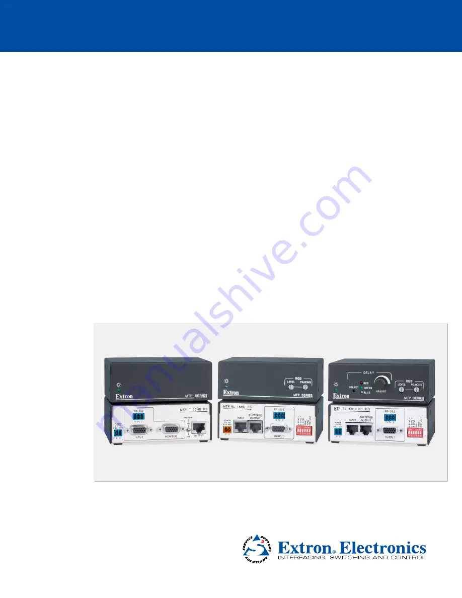
High Resolution Video and Serial Link
MTP Transmitters and Receivers
MTP 15HD RS Series
User Guide
Twisted Pair
Страница 1: ...68 925 02 Rev F 08 11 High Resolution Video and Serial Link MTP Transmitters and Receivers MTP 15HD RS Series User Guide Twisted Pair...
Страница 2: ...machen da im Inneren des Geh uses dieses Produktes gef hrliche Spannungen die nicht isoliert sind und die einen elektrischen Schock verursachen k nnen herrschen Achtung Lesen der Anleitungen Bevor Si...
Страница 3: ...a residential area is likely to cause harmful interference in which case the user will be required to correct the interference at his own expense NOTE This unit was tested with shielded cables on the...
Страница 4: ...Twisted Pair Cable Termination 14 Skew Delay Compensation 15 SEQ Receiver Skew Compensation 15 Non SEQ Receiver Skew Compensation 15 Reference Information 16 Specifications 16 Part Numbers Optional A...
Страница 5: ...products that are compatible with Extron STP201 or CAT 7 cable only In this guide any reference to these products refers to either family unless explicitly stated NOTE For clarity and where applicabl...
Страница 6: ...NOTE If there is only one receiver in the system you can shift a jumper in that receiver see Receiver Jumpering on page 5 to allow bidirectional RS 232 communications and change a DIP switch setting s...
Страница 7: ...page 10 using Extron Enhanced Skew Free A V UTP cable STP201 cable or CAT 5 5e 6 or 7 cable terminated with RJ 45 connectors NOTES The non C7 transmitter and receiver are designed for and perform best...
Страница 8: ...0 90 m 400 120 m 2048x1080 250 75 m 300 90 m 300 90 m 400 120 m HDTV 720p 250 75 m 300 90 m 400 120 m 500 150 m HDTV 1080i 250 75 m 300 90 m 300 90 m 400 120 m HDTV 1080p 250 75 m 300 90 m 300 90 m 40...
Страница 9: ...jumper JMP1 on the serial data top board and shift the jumper to bridge the jumper block see figure 2 below 4 Place the top cover back into place 5 Reinstall the four screws removed in step 2 If any...
Страница 10: ...all power sources and signal cables are disconnected 2 If necessary configure the receiver jumpers see Receiver Jumpering on page 5 3 If applicable mount the MTPs see Mounting on page 20 4 Connect th...
Страница 11: ...e displayed image Adjust the knob while viewing the displayed image to set the level that provides the best picture quality NOTE For best results when using an RL receiver connect a load to the buffer...
Страница 12: ...e the video signal that is selected by the Select button d for skew adjustment using the Delay control f The LED of the selected color flashes when skew compensation for the selected video signal has...
Страница 13: ...ection on page 13 before wiring the connector b Input video connector Connect a computer video source to this 15 pin HD connector for high resolution video input see figure 5 5 1 15 11 6 10 Female Fig...
Страница 14: ...er the wires can be easily pulled out even if tightly fastened by the captive screws Do not tin the wires Tinned wire does not hold its shape and can become loose over time e Pre Peak switch The Pre P...
Страница 15: ...uffered output connector of an RL receiver to this RJ 45 female connector c Buffered output connector Connect one end of a TP cable to this female RJ 45 connector Connect the free end of the same TP c...
Страница 16: ...onent S video Composite Figure 8 Receiver DIP Switch Settings z z Sync on Green SOG switch Set this switch up for RGsB video when the input is RGBHV or RGBS or down to output RGBHV RsGsBs or RGBS vide...
Страница 17: ...itable for use in air handling spaces or in wall cavities The power supply is to be located within the same vicinity as the Extron A V processing equipment in an ordinary location Pollution Degree 2 s...
Страница 18: ...ee A V UTP cable use the TIA EIA T568A standard only Figure 10 TP Cable Termination Diagram NOTES RJ 45 termination with CAT 5 5e or 6 cable for non C7 units only or STP201 or CAT 7 cable for C7 units...
Страница 19: ...l for determining skew 3 Adjust the leftmost video signal as follows NOTE The SEQ receiver cannot shift the rightmost video image to the left a Use a small screwdriver to press and release the Select...
Страница 20: ...B Y of component video 0 3 Vp p for C of S video Minimum maximum levels 0 3 V to 1 45 Vp p Impedance 75 ohms Horizontal frequency 15 kHz to 130 kHz Vertical frequency 30 Hz to 150 Hz Return loss 30 dB...
Страница 21: ...captive screw connector Receivers 1 set of proprietary signals on a female RJ 45 jack Serial control port output input MTP C7 T 15HD RS MTP T 15HD RS 1 set of proprietary signals on a female RJ 45 jac...
Страница 22: ...d labor NOTE All nominal levels are at 10 NOTE Specifications are subject to change without notice Part Numbers Optional Accessories Cables and Connectors Part Numbers MTP Transmitter and Receivers fo...
Страница 23: ...escription Part Number VGA connector cable 26 238 xx SYM BNC Female Mini High Resolution cable 26 531 xx Extron Enhanced Skew Free A V UTP cable cut various lengths 26 569 xx Extron Enhanced Skew Free...
Страница 24: ...r multi unit rack assembly the operating ambient temperature of the rack environment may be greater than room ambient temperature Therefore install the equipment in an environment compatible with the...
Страница 25: ...e unit on a rack shelf follow the instructions provided with the shelf accessories Back of the Rack Mounting Procedure The MTP can be mounted to the rear of a rack using the Extron MBB 100 1 8 and 1 4...
Страница 26: ...ive please call Extron and ask for an Application Engineer to receive an RA Return Authorization number This will begin the repair process USA 714 491 1500 Europe 31 33 453 4040 Asia 65 6383 4400 Japa...