2-9
IPI 100 and IPI 200 Series • Installation
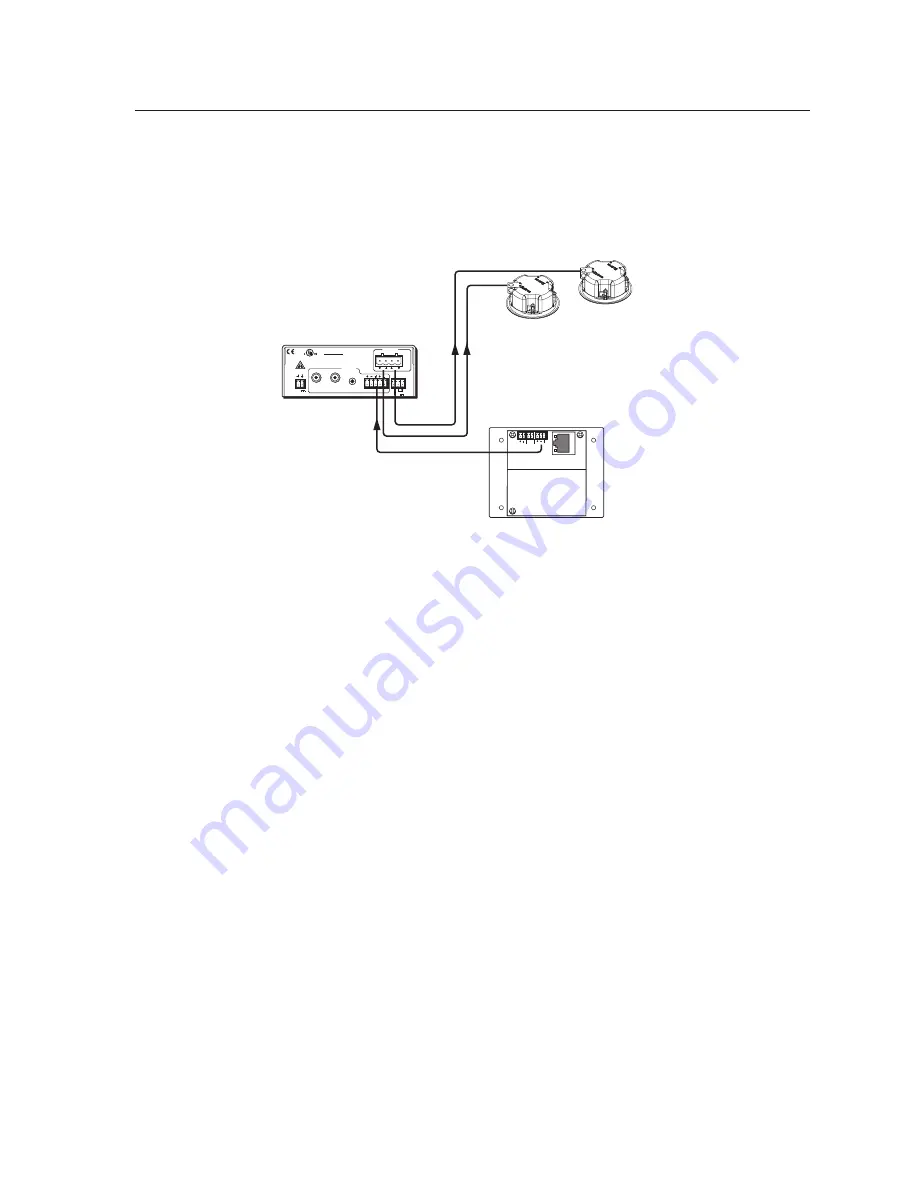
Intercom with amplifier
The MLC’s Audio Out 2‑pole captive screw connector outputs a ‑10 dBV audio
signal that can be routed to an MPA 152 or any external audio amplifier, then to
speakers.
1.
Cable the system as shown in the following diagram.
MPA 152
IPI 201
POWER
12V
3A MAX
OUTPUT
4/8
OHMS
CLASS 2 WIRING
DO NOT GROUND
OR SHORT
SPEAKER OUTPUTS!
INPUTS
L
R
L
R
REMOTE
VOL/MUTE
10V
50mA
L
MPA 152
R
C
US
LISTED
17TT
AUDIO/VIDEO
APPARATUS
SI 3CT LP
Ceiling
Speakers
POWER
RELAY
C NO
AUDIO OUT
LAN
2.
Power on the equipment.
3.
Make fine adjustments to output level using the
Remote Line
slider in the
Advanced Settings
part of the HelpDesk software. The external amplifier (the
MPA 152 in this example) must be adjusted properly to avoid any audio signal
clipping or audio distortion.
4.
If desired, use the software to adjust to minimum levels the IPI’s speaker
output.
Содержание IPI 101 AAP
Страница 4: ......
Страница 8: ...Table of Contents cont d IPI 100 and IPI 200 Series Table of Contents iv...
Страница 14: ...Preface cont d IPI 100 and IPI 200 Series Preface 1 6...
Страница 24: ...Installation cont d IPI 100 and IPI 200 Series Installation 2 10...
Страница 25: ...IPI 100 and IPI 200 Series 3 Chapter Three Operation Front Panel Features and Operation Button Operation...
Страница 28: ...IPI 100 and IPI 200 Series Operation 3 4 Operation...
Страница 76: ...SIS Programming and Control cont d IPI 100 and IPI 200 Series SIS Programming and Control B 18...
Страница 77: ...IPI 100 and IPI 200 Series C Appendix C Mounting Mounting the IPI 100 Series Mounting the IPI 200 Series...
Страница 80: ...Mounting cont d IPI 100 and IPI 200 Series Mounting C 4...
Страница 81: ...IPI 100 and IPI 200 Series D Appendix D Button Labels Installing or Replacing Button Labels...


