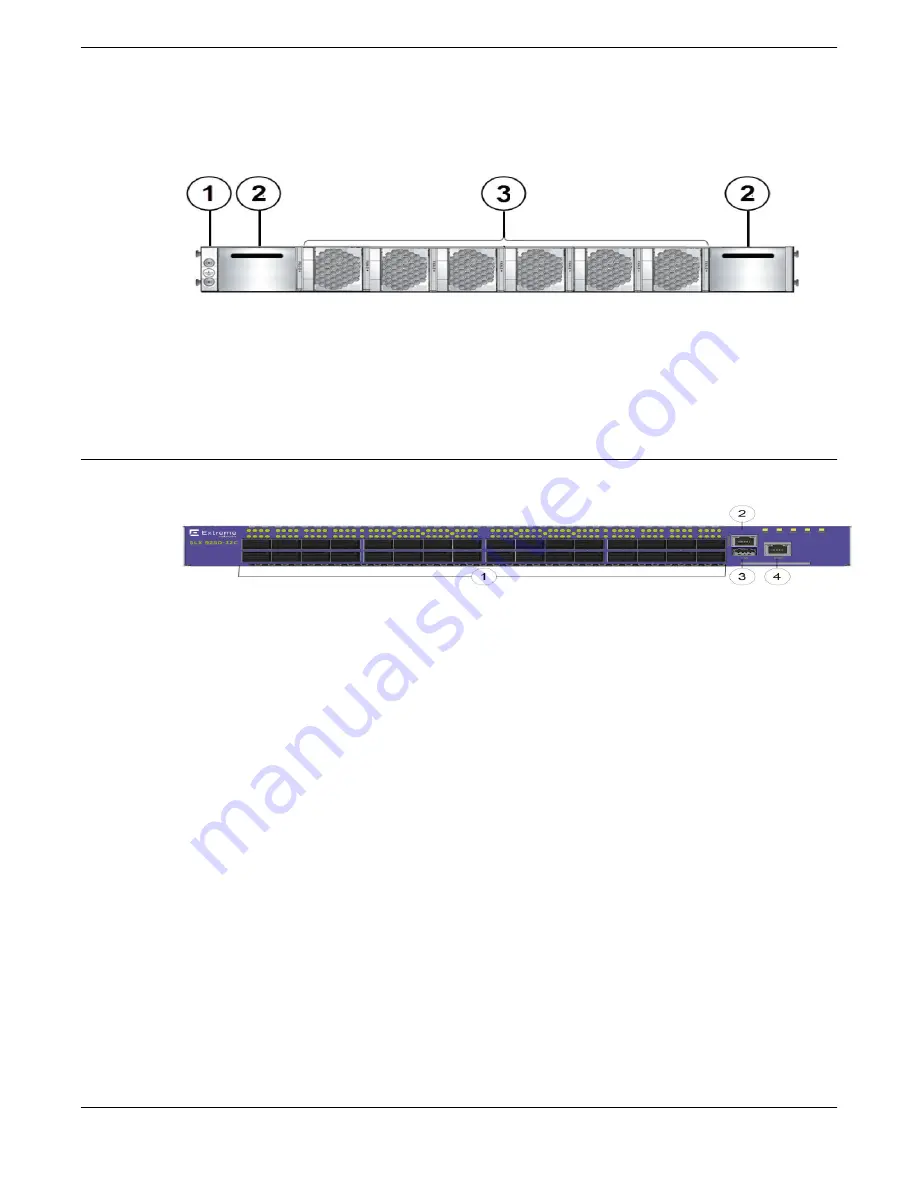
The following illustration shows the rear view of the SLX 9250 Switch.
Figure 1: SLX 9250 Switch rear view with power supply and fan assemblies
1. Grounding point
2. Power supply slots (unpopulated)
3. Fan modules
For more device details, refer to the
ExtremeSwitching SLX 9250 Technical Specifications
on page 70
Port-side view of the SLX 9250 Switch
The following illustration shows the port-side view of the SLX 9250 Switch models.
1. 40Gbps/100Gbps QSFP28/QSFP+ Ethernet ports
2. Console port: RJ45
3. USB A port
4. Management port: RJ45
Figure 2: Port-side view of the SLX 9250-32C Switch
Most of the front-panel ports on the SLX 9250-32C Switch operates in either 100 gigabit or 40 gigabit
mode, and each port can be partitioned into data lanes through the use of breakout cables. This means
that a given physical port can correspond to either two or four logical ports.
In 100-gigabit mode, each port can be partitioned into four 25-gigabit data lanes.
In 40-gigabit mode, each port can be partitioned into four 10-gigabit data lanes.
Logical port numbers are assigned depending on whether the physical ports are partitioned into data
lanes. If there is no partitioning/channelizing, the logical port numbers correspond to the physical port
Device Overview
Port-side view of the SLX 9250 Switch
ExtremeSwitching SLX 9250 Hardware Installation Guide
15


