individual units maintain their original unit numbering, even if the position of one or more units in the
stack is changed.
For example, when the stack is initially powered, the base unit becomes unit 1 and the unit that the
base unit connects to (through the Cascade Down cable) becomes unit 2 (and the next unit is unit 3
and so on), until the maximum stack configuration (up to eight units) is reached. If the base unit is
changed to another unit in the stack, the new base unit keeps its original unit number in the stack.
When a switch participates in a stack configuration, a stack MAC address is automatically assigned
during stack initialization. The stack MAC address is the base unit MAC address plus 1. If another
nit in the stack is assigned as the base unit, the new stack MAC address is the MAC address of the
new base unit plus 1. The original stack IP address still applies to the new base unit.
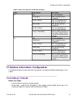
If an assigned base unit fails, the next unit in the stack order automatically becomes the new
temporary base unit. This change is indicated by the Base LED on the temporary base unit LED
display panel moving to a steady amber state.
This automatic failover is a temporary safeguard only. If the stack configuration loses power, the
temporary base unit will not power up as the base unit when power is restored. Also, if the original
unit rejoins the stack, it will not resume base unit status. For this reason, always assign the
temporary base unit as the base unit until the failed unit is repaired or replaced.
Important:
If the temporary base unit is not assigned as the new base unit, and the temporary base unit
fails, the next unit in the stack order becomes the temporary base unit. This process continues
after successive failures until only two units are left in the stack.
Regardless of stack configuration, the following applies:
• When power is applied to the stack the base unit initializes, typically within 60 seconds, and the
entire stack powers up as a single logical unit.
• A RS-232 communications cable can be attached to the console port of any switch in the stack
to establish a console connection.
• A software upgrade can be performed on the stack from any switch using the console interface,
a Telnet session, the Enterprise Device Manager interface, or any SNMP-based management
software.
• The stack can be managed using a Telnet session, Enterprise Device Manager interface, or
any SNMP-based management software through any stack switch port.
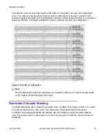
Cascade Down
The system automatically numbers the physical units based on the designated base unit (Unit 1). In
a cascade down configuration, the base unit is physically located as the top unit in the stack. The
cable connected to the Cascade Down connector of the base unit terminates in the Cascade Up
connector on the next unit in the stack which is physically located below the base unit. This next unit
is designated Unit 2. The stack is wired downward through the units and the system continues to
number in this manner throughout the stack. In this configuration, the base unit discovers the stack
in a cascade down (stack down) direction.
Installing the Switch
February 2020
Installing Ethernet Routing Switch 3600 Series
28

