Extreme Networks Campus Controller E2122 Скачать руководство пользователя страница 16

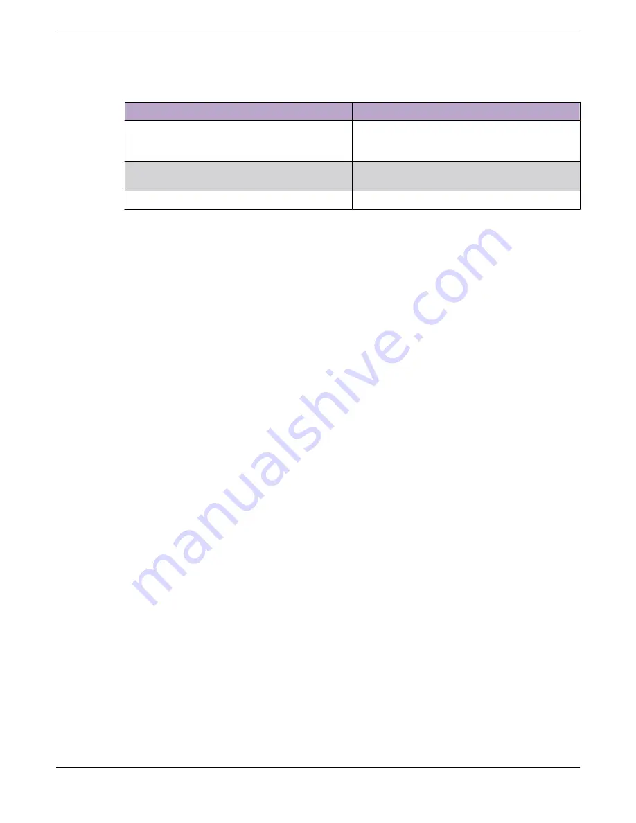
Table 4: Power supply status LED indicator patterns (continued)

Power supply condition

Description

Power supply warning events where PS continues

to operate - high temp, high power, high current,

and slow fan

1Hz blinking amber

Power supply critical event causing a shutdown,

failure, OCP, OVP, fan fail

Amber

Power supply firmware updating

2Hz blinking green

Related Topics

Power Source and Power Supply Information

 on page 12

Connect to a Power Source

 on page 12

Install a Power Supply

 on page 14

Remove a Power Supply

 on page 15

Replace a Power Supply

Power Source and Power Supply Information

16

Extreme Campus Controller™

Содержание Campus Controller E2122

Страница 1: ...Extreme Campus Controller Installation Guide 9036938 00 Rev AA April 2021 ...

Страница 2: ...tworks and the Extreme Networks logo are trademarks or registered trademarks of Extreme Networks Inc in the United States and or other countries All other names including any product names mentioned in this document are the property of their respective owners and may be trademarks or registered trademarks of their respective companies owners For additional information on Extreme Networks trademark...

Страница 3: ...ly 14 Remove a Power Supply 15 Replace a Power Supply 15 Initial Network Connection and Configuration 17 Configure the Management Interface via Console Port 17 Configure the Management Interface via Management Port 19 Connect the Data Ports 20 Install a Transceiver 21 Regulatory Compliance Information 23 Federal Communications Commission FCC Notice 23 Industry Canada Class A 23 Japan VCCI Voluntar...

Страница 4: ...in the text When a feature function or operation pertains to a specific hardware product the product name is used When features functions and operations are the same across an entire product family such as ExtremeSwitching switches or SLX routers the product is referred to as the switch or the router Table 1 Notes and warnings Icon Notice type Alerts you to Tip Helpful tips and notices for using t...

Страница 5: ... components displayed within square brackets are optional Default responses to system prompts are enclosed in square brackets x y z A choice of required parameters is enclosed in curly brackets separated by vertical bars You must select one of the options x y A vertical bar separates mutually exclusive elements Nonprinting characters such as passwords are enclosed in angle brackets Repeat the prev...

Страница 6: ...iption of your network environment such as layout cable type other relevant environmental information Network load at the time of trouble if known The device history for example if you have returned the device before or if this is a recurring problem Any related RMA Return Material Authorization numbers Subscribe to Product Announcements You can subscribe to email notifications for product and sof...

Страница 7: ...edback icon and complete the online feedback form Access the feedback form at https www extremenetworks com documentation feedback Email us at documentation extremenetworks com Provide the publication title part number and as much detail as possible including the topic heading and page number if applicable as well as your suggestions for improvement Preface Providing Feedback Extreme Campus Contro...

Страница 8: ...ient distribution between controllers E2122 back panel features Figure 1 E2122 back panel layout Callout Description 1 Power supply module 1 2 Power supply module 2 bay for redundant power supply ordered separately 3 Port 1 Data Port 1 1 10GbE RJ45 4 Port 2 Data Port 2 1 10GbE RJ45 5 VGA port do not use 6 RJ45 serial A port 7 Admin management port 1GbE RJ45 8 USB 2 0 or 3 0 ports 9 Not used 10 Por...

Страница 9: ...ED Indicator Patterns The hard drive has one LED indicator visible from the front of the system a green LED for disk activity E2122 Controller Overview Hard Drive LED Indicator Patterns Extreme Campus Controller 9 ...

Страница 10: ...rt 3 Mount the controller on a rack or a table 4 Connect the controller to a power source 5 Install a power supply For power supply troubleshooting details see remove a power supply or replace a power supply 6 Configure the controller via console port or management port 7 Connect the data ports 8 Install a transceiver What to Do Next Read and review the regulatory and compliance information Verify...

Страница 11: ... antistatic wrist strap while performing the following procedures About This Task Mount the controller on a rack or a table Procedure 1 If you are installing the controller in a rack read the Rail Kit Installation instruction sheet included with the rack mounting kit 2 Install the rails and mount the controller in the rack as instructed If you are table mounting the controller ensure at least 6 cm...

Страница 12: ...plate The controller comes with an optional front panel faceplate attached to the unit You can monitor the system status indicators with the faceplate in place Connect to a Power Source Learn how to connect the controller to a power source About This Task After installing the controller to a rack or to a table connect the controller to a power source To view port information see E2122 back panel f...

Страница 13: ... a power distribution unit PDU 5 Power on the controller The power button is on the front control panel as shown in E2122 front panel layout and front control panel Figure 2 E2122 front panel layout Callout Description 1 Hard disk drive bays 2 Front video controller 3 USB 2 0 or 3 0 ports Note For USB key storage only Although the controller has 5 USB connectors two on the front panel and three on...

Страница 14: ...pply About This Task Install a power supply to the controller for normal operation Procedure 1 Remove the insert from the chassis power supply bay 2 Insert the power supply module into the power supply bay 3 Push the power supply module into the bay until it locks into place Related Topics Power Source and Power Supply Information on page 12 Connect to a Power Source on page 12 Remove a Power Supp...

Страница 15: ...power supply is removed with the system powered on the full power load is picked up by the remaining power supply Note The system ships with just one power supply and you have the option to purchase the additional redundant power supply Ordering Part No 30527 WS PSI 1100W 01 Important The system requires one power supply to operate the system normally Remove and replace only one power supply at a ...

Страница 16: ...linking amber Power supply critical event causing a shutdown failure OCP OVP fan fail Amber Power supply firmware updating 2Hz blinking green Related Topics Power Source and Power Supply Information on page 12 Connect to a Power Source on page 12 Install a Power Supply on page 14 Remove a Power Supply on page 15 Replace a Power Supply Power Source and Power Supply Information 16 Extreme Campus Con...

Страница 17: ...t interface using the console port About This Task Configure the controller management interface via console port during initial setup Note The E2122 must be upgraded to the latest Extreme Campus Controller firmware before installing the controller on the network Procedure 1 Connect the serial port of the laptop to the E2122 console port If the laptop does not support RS232 interface then obtain a...

Страница 18: ...ly settings and exit or a number for repeating the setup 8 Connect to a port on which management access was enabled during the CLI Wizard Setup 9 Open a web browser and type the following in the address bar https Your_Mgmt_Ipaddress 5825 The Extreme Campus Controller login screen is displayed 10 Log in as follows Username admin Password abc123 or the password that was created when setting up the i...

Страница 19: ...s in the 192 168 10 0 24 subnet 3 Open a web browser and type the following in the address bar https 192 168 10 1 5825 192 168 10 1 is the default IP address on the controller management port The Extreme Campus Controller login screen is displayed 4 Log in as follows Username admin Password abc123 Select Login 5 Complete the installation to configure the E2122 controller for new deployments 6 Disc...

Страница 20: ...een or blinking green If the activity link LED is off perform the following steps until it is powered on a Verify that the cabling being used is Category 5 or better Category 6 or better for 10 Gbps connection with an impedance between 85 and 111 ohms and a maximum length of 100 meters 328 feet b Verify that the device at the other end of the twisted pair segment is turned on and is properly conne...

Страница 21: ...er and from the connectors on each end of the cable b Insert the cable connector into the transceiver connector until it clicks into place c Plug the other end of the cable into the appropriate port on the other device Some fiber optic cables may be terminated at the other end with two separate connectors one for each fiber optic strand In this case ensure that the transmit fiber optic strand from...

Страница 22: ...dication Network speed right Solid amber 1000Mbps 1Gbps Solid green 10000Mbps 10Gbps Link activity left Off No link Solid green Active link Blinking green Data traffic activity Table 7 SFP port LEDs data ports 3 and 4 LED color and status Description Off A link has not been established Blinking amber 4Hz blinking amber indicates a problem with the link Solid green Valid link with no active traffic...

Страница 23: ...t installed and used in accordance with the manufacturer s instruction manual may cause harmful interference to radio communications Operation of this product in a residential area is likely to cause harmful interference in which case you will be required to correct the interference at your own expense This device complies with Part 15 of the FCC rules Operation is subject to the following two con...

Страница 24: ...ent is used in a domestic environment radio disturbance may arise When such trouble occurs the user may be required to take corrective actions BSMI EMC Statement Taiwan This is a class A product In a domestic environment this product may cause radio interference in which case the user may be required to take adequate measures Hazardous Substances This product complies with the requirements of Dire...

Страница 25: ...It has been determined by the European Parliament that there are potential negative effects on the environment and human health as a result of the presence of hazardous substances in electrical and electronic equipment 4 It is the user s responsibility to utilize the available collection system to ensure WEEE is properly treated For information about the available collection system please contact ...

Страница 26: ...Supplement to Product Instructions Supplement to Product Instructions Regulatory Compliance Information 26 Extreme Campus Controller ...

Страница 27: ...console port 17 management port 17 mount the controller rail kit 11 table mount 11 N network configuration 17 network connection 17 notices 4 P port LEDs data ports 1 and 2 21 data ports 3 and 4 21 management port 21 power source 12 power supply 12 power supply installation 14 R regulatory and compliance 23 regulatory information 23 regulatory information hazardous Substances 24 Regulatory Stateme...

Отзывы: