2/11/2020
AP305C and AP305CX Hardware User Guide
docs.aerohive.com/330000/docs/help/english/ng/Content/hardware/ap/ap305c-ap305cx.htm?Highlight=ap305c
5/16
Once the bracket is secure, lift the AP and fit the bracket into the circular depression on the bottom of the device. Rotate the
AP clockwise until it clicks in to place. The process is identical for both models.
Mount the AP on a Wall
Use the holes in the accessory wall-mount bracket as a template to mark the wall. Drill holes in the wall and attach the bracket
to the wall using wall screws and wall anchors, if necessary. Attach the AP to the bracket in the same manner as shown in
the previous section. Install external antennas on AP305CX devices. Order external antennas from Extreme Networks (AH-
ACC-ANT-AX-KT).
Lock the AP
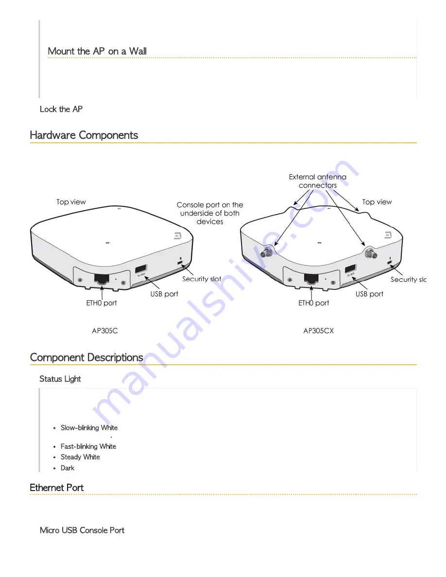
Hardware Components
The hardware components of the AP305C and AP305CX are identified in the illustration below and described in the sections that
follow.
Component Descriptions
Status Light
The status light conveys operational states for system power, firmware updates, Ethernet and wireless interface activity, and
major alarms. The AP305C and AP305CX have a rectangular status light on the top right corner of the chassis. At setup, this
light cycles through the following sequence:
Slow-blinking White
: The device is attempting to establish a connection or has established a CAPWAP connection with
ExtremeCloud IQ
.
Fast-blinking White
: The device is performing a IQ Engine or ExtremeCloud IQ upgrade.
Steady White
: The device has successfully established a CAPWAP connection and is operating normally.
Dark
: Power is off.
Ethernet Port
The ETH0 port is autosensing 10/100/1000G BASE-T/TX Mbps, with IEEE 802.3af- or 802.3at-compliant PoE, and requires
Cat5 or better cable.
Micro USB Console Port


