- 9 -
Installing Accessories
IV
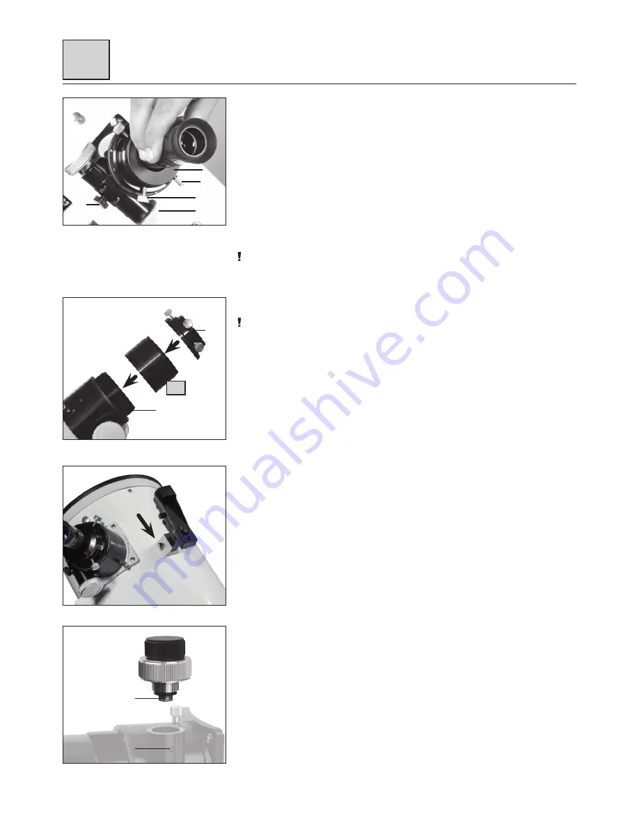
Inserting the Eyepiece
(Fig. 12)
1. Insert the 1.25" eyepiece (Fig. 1, J) into the eyepiece holder (Fig. 12, 15).
2. Tighten the clamp screw (Fig. 12, 17) slightly.
3. Look through the eyepiece and turn the focusing wheel of the focusing drive (Fig. 12, 13)
right or left to focus the image.
4. When using a 2" eyepiece remove the 1.25" eyepiece adapter (Fig. 12, 15) from the holder
first.
5. Now insert the 2" eyepiece and fix it with the lock screw.
The eyepiece holder is equipped with a friction screw (Fig. 12, 14) on its bottom side and
with two fixing screws (Fig. 12, 14a) on its top side. Adjust the friction screw so that the
focusing drive can be moved sensitively. Additionally the focuser can be fixed with the fixing
screws to avoid unintentional adjustment.
NOTE!
Loosen the fixing screws on the focuser completely before you start focusing! Never tighten
the friction screw and fixing screws too firmly.
Attaching a Spacer Sleeve
(Fig. 12a)
NOTE!
A spacer sleeve resolves focusing problems when the focusing point is not close to the
eyepiece extension. With a spacer sleeve it is, for example, possible to use the telescope for
photography or to use eyepieces with the telescope that offer an extreme focal position. It
is bridging the optical distance by its own length. When using a spacer sleeve, it is also no
longer necessary to turn out the eyepiece extension until it stops. It also increases mechanical
stability.
1. Unscrew the eyepiece holder (Fig. 12, 2a) and remove it from the eyepiece extension
(Fig. 12, 2).
2. Screw the spacer sleeve (Fig. 12, U) onto the eyepiece extension (Fig. 12, 2).
3. Screw the eyepiece holder (Fig. 12, 2a) onto the spacer sleeve (Fig. 12, U).
4. By screwing two or more optional spacer sleeves together, the optical distance can be
extended additionally.
Attaching the red dot viewfinder
(Fig. 13)
Slide the red dot viewfinder holder into the track of the pre-installed holder base. Secure the
red dot viewfinder in place by tightening the screws on the side of the pre-installed bracket.
Attaching a 10:1 Micro Reduction Unit (optional)
(Fig. 14)
A 10:1 micro reduction unit is available as an optional accessory and can be attached instead
of the normal reduction. It allows for normal focusing speed as well as for a focusing speed
that is reduced by ten times and therefore provides a very fine focusing. The optional 10:1
micro reduction unit is a special order from Germany, which means it can take several weeks
for delivery.
1. Loosen the hex screw at the bottom side of the right focusing wheel with a hex wrench.
2. Pull out the focusing wheel.
3. Insert the 10:1 micro reduction unit and tighten the hex screws of the drive shaft
(Fig. 14, X) and the hex screw of the housing (Fig. 14, Y) until sturdy.
Fig. 12
13
17
15
14
a
14
Fig. 14
X
Y
Fig. 13
Fig. 12a
2a
2
U


