- 8 -
III
Attaching the OTA
STEP 8 (Fig. 10):
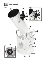
1. Attach both altitude wheels (Fig. 1, H) with the fixing screws
(Fig. 1, T) to the right and left side of the OTA.
NOTE!
Make sure that the 'noses' on one side (Fig. 10, X) are pointing in
the direction of the clamp screws (Fig. 10, 5a) for the brackets and
that the lateral guides of the altitude wheels are pointing at one
another.
STEP 9 (Fig. 11):
1. Put the OTA with the attached altitude wheels into the half round
sections of the side parts (Fig. 11, 9).
NOTE!
Make sure that the aperture of the OTA (Fig. 11, 3) is pointing in the
direction of the front part (Fig. 11, 10) when attaching it.
2. Hold the OTA with one hand until it is balanced correctly. If
neccessary, move the OTA a little to another position within the
brackets (Fig. 11, 5) to establish a balance. Also when changing
the accessories a new balancing of the OTA is required.
NOTE!
Balancing is important because otherwise the tube could tip over at a
low imbalance and could be damaged.
3. Adjust the lateral guides (Fig. 11, 7a) of the altitude. Use a
suitable 2mm hex wrench. The side floating and the friction of the
altitude axis can be adjusted by evenly tigthening the four hex
screws (two per lateral guide).
NOTE!
Be careful not to over tighten the screws in order to avoid damage or
premature wear.
Fig. 10
X 5a
3
Fig. 11
Setup
5
9
10
7a


