EX9212LoRa series User Manual
EX9212LoRa Series
• Manual Version 1.1.0 • 2019-09-19
www.topsccc.com
11
3.5.1 DC-IN Power Outlet
LoRa Gateways are powered by a 9~24V DC (Inner positive, outer negative) power supply and 1.0A
current. Connecting the AC plug to the AC power socket and put the DC Jack plug into the outlet of
device. The “SYS” (or “PWR”) red color LED will be ON when power properly supplied. Terminal
Block (2 wires) power supply is alternative.
3.5.2 Ethernet LAN Port
The connector for LAN connection is a general RJ45 socket. Simply connect it to network Switch
Hub. When the connection is made, the LAN LED indicator light on. When data start transmission,
Tx/Rx LED indicator will blink during data transferring or receiving.
3.5.3 Serial Port (RS-232:half-duplex/485)
Connecting the Serial Port Cable from the LoRa Gateway to the Serial Interface device. Follow the
parameter setup procedures to configure the converter (see the following chapters).
3.5.4 2DI / 2DO port
Please refer the specs sheet of EX9212LoRa-DIO.
3.5.5 Reset Button
In any case you forgot the password or have incorrect settings must to set Converter back to default,
use the Reset button. At first, power on the Converter, then press Reset button as per below list to
reboot or restore to the factory default.
1 Second
– no action
2 ~ 4 Seconds -- reboot
5 Seconds up -- restore factory default
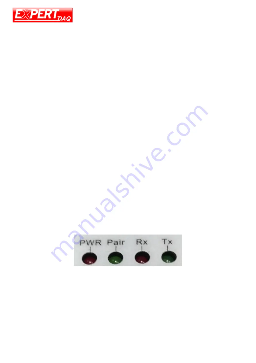
3.6 LED Indicators
PWR (Red):
Power indicator. When the power is on, the LED will be on.
Tx (Green):
Data sending indicator. When data sending to the network, this LED will blink.
Rx (Red):
Data received indicator. When data receiving from the network, this LED will blink.


