


becomes a gate control for the Freeze function, freezing the buffer when the CV goes over
approximately 1V.
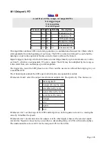
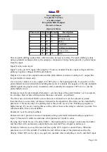
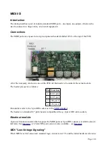
M-8 Chaos
X & Y influence the chaos
A & B are chaotic outputs
Z is speed
Parameter Min Max Default
Description
0
-64 32
0
Range.
1
0
11
0
Outputs.
2
-64 64
32
Atten A.
3
-64 64
32
Atten B.
4
-32 32
0
Offset A.
5
-32 32
0
Offset B.
6
0
1
0
Clamp.
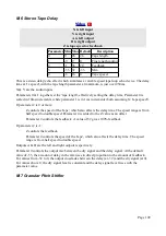
This algorithm generates chaotic CVs and/or gates according to the
The X & Y inputs set parameters of the equations – X affects 'r' (aka 'ρ'), and Y affects 'b' (aka 'β').
With the CVs at 0V, the parameters are the classic values as studied by Lorenz (28 and 8/3
respectively).
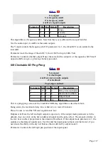
The A & B outputs generate the x, y or z values of the Lorenz system, or gates based on these
values, according to parameter 1 as follows:
Parameter 1 Output A
Output B
0
x
z
1
y
z
2
x
y
3
x-based gate z
4
y-based gate z
5
x-based gate y
6
x
z-based gate
7
y
z-based gate
8
x
y-based gate
9
x-based gate z-based gate
10
y-based gate z-based gate
11
x-based gate y-based gate
When a gate output is chosen, the output is 5V when the x/y/z value is above zero, and 0V when the
value is below zero. This comparison happen after the scale/offset from parameters 2-5, so the
precise gates obtainable are affected by these parameters.
21 https://en.wikipedia.org/wiki/Lorenz_system
Page 111