background image

26

MANUGENEX7xx 

Operating Instructions

VER 2.00

10 System Settings

System Settings

eX Series 700 HMI products have a system settings interface to allow configuration of system options. 

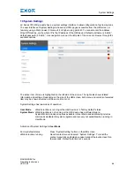
The user interface of System Settings is based on HTML pages accessible from the HMI screen or 

remotely using a Web browser Chrome v44 or higher using port 443. To connect enter the address 

https://IP/machine_config where IP is the IP address of the HMI device. Default username is “admin”, 

default password is “admin”. Use navigation menu on the left side of the screen to browse through the 

available options. 

The active item of menu is highlighted on the left side of the screen. The right side shows related 

information and settings. Depending on the size of the HMI screen, both menu and content of selected 

item may be shown on screen at the same time or not. 

System Settings has two modes of operation: 

User Mode


JMobile runtime is running or the HMI device is in “factory default” status.

System Mode

  JMobile runtime is not running or the HMI device has a software failure. 


System Mode includes all options available in User Mode and additionally includes  


commands dedicated to system upgrade and recovery not available when running in  

  User 

Mode.

Activation of System Settings in 

User Mode

:

Factory default status   

Press “System Setting” button on the HMI screen

JMobile runtime running  

Recall context menu and select “System Settings”. To recall the    


context menu click and hold any unused area of the touchscreen for a  


few seconds. Default hold time is 2 seconds.

Содержание eX705

Страница 1: ...Exor International S p A MANUGENEX7xx Ver 2 00 eX700 Series Operating Instructions Basic User s Manual for eX700 Series Touchscreen Products...

Страница 2: ...tice The information contained in this document is provided for informational purposes only While efforts were made to verify the accuracy of the information contained in this documentation it is prov...

Страница 3: ...9 4 Technical Data 11 4 1 Dimensions 14 4 2 Installation Environment 16 4 3 Safety instruction 17 4 4 Installation Procedure 17 5 Connections 18 5 1 Serial Port 20 5 2 Ethernet Port 20 5 3 Optional p...

Страница 4: ...Operator interface with TFT color 5 widescreen display multitouch projected capacitive touchscreen eX707 Operator interface with TFT color 7 widescreen display multitouch projected capacitive touchsc...

Страница 5: ...vided into three levels of severity DANGER indicates a failure to observe safety rules and such failure may cause death or serious injuries ATTENTION indicates a failure to observe safety rules and th...

Страница 6: ...lding automation The glass projected capacitive touchscreen and the brilliant displays with size up to 21 5 and resolution up to 1920x1080 guarantee great optical performance with the support of multi...

Страница 7: ...61000 4 3 EN 61000 4 4 EN 61000 4 5 EN 61000 4 6 EN 61000 4 8 EN 61000 4 11 EN 61000 4 29 EN60945 The installation of these devices into the residential commercial and light industrial environments i...

Страница 8: ...rect usage of the information contained in the guide An example of this plate is shown in the figure below Note the eX710 label is used as an example for eX700 Series product model name eX710 product...

Страница 9: ...ld immunity test Enclosure 50 60Hz 30A m EN 61000 4 8 Environmental conditions Operating temperature surrounding 20 60 C vertical installation EN 60068 2 14 air temperature Plug in modules and USB dev...

Страница 10: ...of the Exor International S p A Power Supply EN 61000 4 11 Port DC mains Level 0 duration 10ms 20 spaces by 1s Test executed on the 24Vdc of the EUT EN 61000 4 29 Durability information Backlight ser...

Страница 11: ...configurable RS 232 RS 485 RS 422 software configurable Ethernet port 2 10 100Mb 2 10 100Mb 1 10 100 1000Mb USB port 1 Host interface version 2 0 max 500mA 2 Host interface version 2 0 max 500mA Expan...

Страница 12: ...232 RS 485 RS 422 software configurable Ethernet port 2 10 100Mb 1 10 100 1000Mb 2 10 100Mb 1 10 100 1000Mb USB port 2 Host interface version 2 0 max 500mA 2 Host interface version 2 0 max 500mA Expa...

Страница 13: ...oftware configurable Ethernet port 2 10 100Mb with integrated switch 1 10 100 1000Mb USB port 2 Host interface version 2 0 max 500mA Expansion slot 2 Optional Plugin Battery rechargeable Real Time Clo...

Страница 14: ...14 MANUGENEX7xx Operating Instructions VER 2 00 4 1 Dimensions Technical Data Cut out MODEL A B C D E F eX705 147mm 5 78 107mm 4 21 136mm 5 35 96mm 3 78 56mm 2 40 8mm 0 31...

Страница 15: ...F eX707 187mm 7 36 147mm 5 79 176mm 6 90 136mm 5 35 47mm 1 85 8mm 0 31 eX710 282mm 11 10 197mm 7 80 271mm 10 67 186mm 7 32 56mm 2 20 8mm 0 31 eX715 422mm 16 60 267mm 10 50 411mm 16 18 256mm 10 00 56mm...

Страница 16: ...the touch screen of the panel In order to meet the front panel protection classifications proper installation procedure must be followed the borders of the cutout must be flat screw up each fixing sc...

Страница 17: ...kets contained in the fixing kit as shown in figure Technical Data 4 3 Safety instruction For all installation notes please refer to the Installation Guide provided with the product CAUTION Tightening...

Страница 18: ...Operating Instructions VER 2 00 5 Connections 1 USB Port 2 Power Supply 3 Serial port 4 Ethernet Port 0 10 100Mb 5 Ethernet Port 1 10 100Mb 6 Expansion slot for Plugin module 7 SD Card Slot Fig 5 1 Co...

Страница 19: ...ons VER 2 00 1 USB port 2 Ethernet port 2 10 100Mb 3 Ethernet port 1 10 100Mb 4 Serial Port 5 Ethernet port 0 10 100 1000Mb 6 Power Supply 7 2x Expansion slot for Plugin module 8 SD Card Slot Fig 5 2...

Страница 20: ...ramming software The communication cable must be chosen for the type of device being connected Connections SERIAL PORT To operate in RS 485 pins 1 2 and 3 4 must be con nected externally Pin Descripti...

Страница 21: ...module multiple modules configurations are possible Slot 2 and Slot 4 are available only if plugin module has the bus extension connector Each slot carries three communication channels 1 serial inter...

Страница 22: ...g Slot association a module plugged in Slot 1 or into Slot 2 will be the CanPort 0 a module plugged in Slot 3 or into Slot 4 will be the CanPort 1 Below you can find relation between modules and max n...

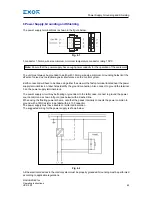
Страница 23: ...tion Also connect to ground the terminal 3 on the power supply terminal block The power supply circuit may be floating or grounded In the latter case connect to ground the power source common as shown...

Страница 24: ...ormation is maintained by the battery hardware real time clock date and time Charge At first installation must be charged for 48 hours When the battery is fully charged it ensures a period of 3 months...

Страница 25: ...than indicated in this document and in the documentation accompanying the product Cleaning Faceplates Getting Started 9 Getting Started eX Series 700 HMI products delivery configuration is based on a...

Страница 26: ...t side shows related information and settings Depending on the size of the HMI screen both menu and content of selected item may be shown on screen at the same time or not System Settings has two mode...

Страница 27: ...of the device Language Configure language used for System Setting menu only System Show information about platform status and timers like System on time backlight on time Logs Enable persistent log f...

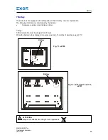
Страница 28: ...x Operating Instructions VER 2 00 11 Unpacking and Packing Instructions Unpacking and Packing Instructions to repack the unit please follow the instructions backwards Fig 11 1 eX705 eX707 eX710 Fig 11...

Отзывы: