background image

User’s  Manual

http://www.exoatletasia.com

ExoAtlet

Ⓡ 

II

34 /  84

Ver  1.0  (2019.03.29.)

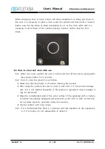
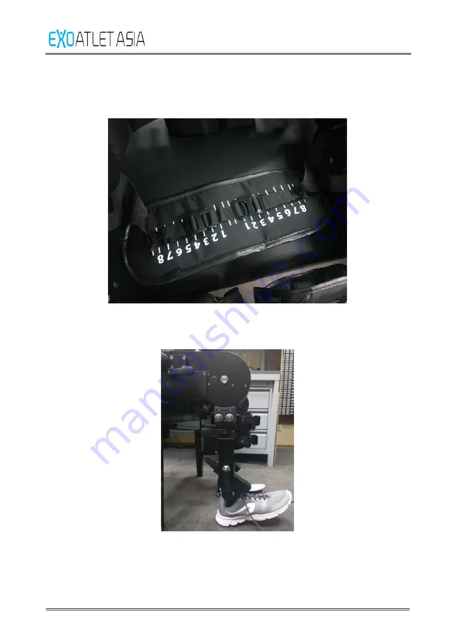
5.3.6. Change the  tightness  of  the  buttock  belt  using  bindings  on  the bottom  side  of 

the  belt  – they  should  be  set  on the  same size  (you can  check  it  by the 
numbers).

5.4. Transferring  to  exoskeleton

5.4.1. Check that exoskeleton sits on the stool firmly (thighs are parallel to the surface).

Содержание EA2010

Страница 1: ...ExoAtlet II User s Manual 이 사용설명서는 사전 통보 없이 제품의 개선을 위해 개정될 수 있습니다 이 사용설명서의 이미지는 실제 제품과 다를 수 있습니다 ...

Страница 2: ...ient population and use environment 11 3 4 Eligibility 11 3 5 Frequently used functions 12 3 6 Specifications 15 3 7 Applied safety standards 17 3 8 Appearance and function 18 3 9 Operating Environment 21 3 10 Storage Environment 21 3 11 Transportation condition 21 3 12 Symbol Include safety sign 22 3 13 Label 25 4 Size adjustment 26 4 1 Shoe insole Shoe sole 26 4 2 Calf length adjustment 27 4 3 C...

Страница 3: ... store after use 41 7 Tablet PC operating 42 7 1 Starting 42 7 2 Trainings 44 7 3 Service 65 7 4 Settings 66 7 5 About 67 7 6 Exit 67 8 ExoCrutch operation 68 8 1 ExoCrutch structure 68 8 2 ExoCrutch available motions 69 8 3 ExoCrutch operation 70 8 4 ExoCrutch operation 71 8 5 Error reset 73 9 Charging the battery 74 9 1 Charging exoskeleton 74 9 2 Charging Tablet PC 75 9 3 Charging ExoCrutch 76 ...

Страница 4: ... you have any questions about the product or need more information about the product please contact the Customer Service Center using the contact information 1 2 Warranty The contents of this document are subject to change without notice The manufacturer is not responsible for any resulting problems losses or damages that result from the use of other performance specifications or other information...

Страница 5: ... minor injury It can also be used to warn of unsafe use or potential damage to equipment Warning Warning These safety signs indicate warnings This indicates a potentially hazardous situation which if not avoided could result in serious injury including death or serious injury Notice This safety label indicates mandatory action This means that the user or patient must follow mandatory instructions ...

Страница 6: ...n 100 kg 2 Pilot Dress Recommendations It is recommended to use sneakers with straps or Velcro Put on comfortable clothes that fit well When using an insole the pilot must use a pair of 1 2 cm size 10 15 mm shoes that is larger than the pilot s shoe size We recommend shoes with removable insole Do not wear boots or shoes with heels It is recommended to use gloves for weight training or cycling We ...

Страница 7: ...and cables that are not provided by our company which may increase the electromagnetic radiation or reduce the electromagnetic immunity of this unit so please be sure to connect the components supplied by us 9 When not using the product turn off the power and store it in an environment suitable for the storage environment 10 Other devices may malfunction due to the electromagnetic interference gen...

Страница 8: ...this document 2 Do not store it in a place where water or foreign matter can enter the equipment when storing it 3 Do not subject the product to strong impacts such as falling over or stepping on the product It may cause malfunction Caution Charging Precautions 1 You must connect the appropriate power source to charge the device Do not disassemble the unit for service or repair while in use For sa...

Страница 9: ...5 Do not wear the exoskeleton too tightly 6 Do not use hard objects in your pocket 7 Do not store any part of the equipment in places that are too cold 20 C or less 8 When connecting or disconnecting power to the unit do not combine or remove it with wet hands 9 Do not use the product for any purpose other than its intended use Misuse can cause injury to the pilot or patient 10 Do not use liquids ...

Страница 10: ...e arthritis acute arthritis or synovitis after total or partial lower extremity joint formation 6 Do not use in patients with dermatological conditions such as hip leg etc where fixing devices are worn 7 Do not use patients with orthostatic hypotension essential hypertension or conditions in which blood pressure can not be controlled 8 Do not use in patients with myocardial infarction angina or is...

Страница 11: ...ovements rely on the functional integrity and interactions of sensory neural networks at the spinal and vertebral levels This complex system can be hampered by a number of neurological conditions such as stroke or spinal cord injury SCI in limited mobility or gait which is a major challenge in nerve rehabilitation Intensive iterative task based training can lead to beneficial nerve regeneration im...

Страница 12: ...rms and is performing a walking exercise at the rehabilitation center under the supervision of a trained physical therapist It is used to improve the gait function of patients with neurological or muscular injuries diseases or disabilities to rebuild muscles and to restore joint motion 3 4 Eligibility This product may only be handled by a professional trainee such as a physical therapist or an exp...

Страница 13: ...s Adjust the width of the pelvis Adjustment of the angle of lead hip reduction Supporting element Thigh Mechanical connection with back and shin Flexion extension of the legs of the patient in the knee and hip joints Adjust the length of the thigh of the exoskeleton Fixation of the thigh bindings Adjustment of the position of the femoral mounts along the sagittal axis forward backward Mounting the...

Страница 14: ...icrocontroller software Integrity control of the onboard computer network Control of the state of all electronic modules Accept and processing commands to control the movement of the exoskeleton from the central cleaning module Generation of control signals for engine control modules Control of the means of light and sound indication of the skeleton Processing of button presses exoskeleton Engine ...

Страница 15: ...System status indication Smart crutch software Connect to the exoskeleton via the Bluetooth module Receive and display information about the state of the skeleton the level of battery power and supported models of traffic Giving the user the ability to select by the control buttons the necessary motion model and send an exoskeleton command to launch the desired motion model Tablet PC Display of in...

Страница 16: ...ax 7 0 A Rechargeable batteries 25 55 V 5700 mAh x 2PCs 2 Remote control crutch Charger Input 100 240 V 50 60 Hz 0 2 A Input Power 5 0 V max 1 0 A Rechargeable battery 3 63 V 2600 mAh Communications Bluetooth Ver 4 0 Wifi Ver 802 11 b g n Dimensions of outer shape 1 Main body 43 80 cm W x 27 50 cm D x 110 160 cm H 2 Crutch Size 74 94 cm Weight Main Body Appr 25 kg Crutch Appr 615 g Classification ...

Страница 17: ...t 0 15 Tablet PC requirements Mobile software is compatible with tablet PC that meet the following specifications Operating system Android v5 1 Lollipop or higher CPU Quad core 1 5 Ghz or higher RAM Internal memory 1 5 GB 16 GB or higher Display resolution 1280 x 800 16 10 Blue tooth version v4 0 Wifi version 802 11 b g n Adaptor set Certified EN IEC 60950 1 ...

Страница 18: ...y Collateral standard IEC 62304 2008 EN 62304 2006 AC 2008 Medical device software Software life cycle processes IEC 62366 2007 EN 62366 2008 Medical devices Application of usability engineering to medical devices EN ISO 15223 1 2016 Medical devices Symbols to be used with medical device labels labelling and information to be supplied Part 1 General requirements EN 50581 2012 Technical documentati...

Страница 19: ...is a device that can fix the user s calf 5 Insole Secure the shoes with the sole that is adjusted to fit the foot size of the pilot 6 Stop button When the button is pressed during operation with the button for temporarily stopping the operation of the machine the machine stops in the state where both feet are standing upright 7 Shoulder straps It is worn on the shoulder with a strap that can fix t...

Страница 20: ...on status of the product 2 Run Stop button Left button Button used to instruct the operation of the product or to stop the device in operation 3 Mode change button Right button Button to select the operation of the product 4 Power button Button to turn on off the product power 5 Charge connector Port used to charge the product 6 handle A handle that can be held by the user 7 support fixture Suppor...

Страница 21: ...set for charging the main body battery complied with EN IEC 60950 1 2 Smart car battery charger set C type USB Adapter set to charge the smart crutches battery complied with EN IEC 60950 1 3 8 4 Sold separately 1 Tablet PC set A portable PC that installs an application to run products and includes an adapter complied with EN IEC 60950 1 ...

Страница 22: ...0 Storage Environment Temperature 5 40 Relative humidity 80 Non condensing Pressure 50 kPa 106 kPa 3 11 Transportation condition Caution 1 Before carry the device separate all components and carry them in the designated box packed with buffer 2 Please carry more than one person while holding the bottom of the packing box with both hands 3 Transportation Environment Temperature 30 60 Relative humid...

Страница 23: ... and Packaging label 3 Date of Manufacture Product label and Packaging label 4 Manufacturer Product label and Packaging label 5 Use by date Product label and Packaging label 6 TYPE BF APPLIED PART Product label and Packaging label User s manual 7 Generation of RF Electromagnetic Wave Energy Product label and Packaging label User s manual 8 Ban of general disposal Disposal of designated disposal fa...

Страница 24: ...e risk of fingers can pinch Moving part 14 Direct current D C charge terminal connection of device side Product label 15 Can be recycled as corrugated paper Product packaging 16 Keep dry Product packaging 17 Keep away from sunlight Product packaging 18 Temperature limit 10 40 Product label 19 Humidity limitation 20 80 Product label 20 Atmospheric pressure limitation 70kPa 106 kPa Product label ...

Страница 25: ...on Position 21 Direction of load Product packaging 22 Fragile handle with care Packaging label 23 Stand by On the product s power button 24 Authorized representative in the European Community Product label and Packaging label 25 EU CERTIFICATION MARK Product label and Packaging label User s manual ...

Страница 26: ...User s Manual http www exoatletasia com ExoAtletⓇ II 25 84 Ver 1 0 2019 03 29 3 13 Label 3 13 1 Main Body 3 13 2 Remote control crutch 3 13 3 Packaging label ...

Страница 27: ...stment 4 1 Shoe insole Shoe sole 4 1 1 Choose the relevant insole sole from the set and place it on the bracket Figure 1 4 1 2 Fasten the screws with the enclosed driver In case of using soles you should use longer screws from the tools kit and fasten the screws from the other side Figure 2 ...

Страница 28: ...and loosen two cam levers 4 2 2 As shown in Figure 4 Adjust sizes by the size lines and push down the cam levers to fix them Figure 3 Figure 4 4 3 Calf depth adjustment 4 3 1 As shown in Figure 5 Pull out and loosen the cam lever 4 3 2 As shown in Figure 6 Adjust sizes by the size lines and push down the cam lever to fix it Figure 5 Figure 6 ...

Страница 29: ...lines and push down the cam lever to fix it If the lower drive is not positioned right it will be difficult to fix cam lever Figure 7 Figure 8 4 5 Thigh depth adjustment 4 5 1 As shown in Figure 9 Pull out and loosen the cam lever 4 5 2 Adjust sizes by the size lines 4 5 3 As shown in Figure 10 Push down the cam lever to fix it You can adjust the pressure by rotating cam lever before pushing it do...

Страница 30: ...gure 11 Remove the previous back pad Place the required back pad Figure 11 Figure 12 4 7 Adjust pelvic floor area 4 7 1 As shown in Figure 13 Pull out and loosen two cam levers 4 7 2 As shown in Figure 14 Pull out the lever Rotate the lever to adjust the desired width rotating clockwise widens the pelvis Figure 13 lever Figure 14 ...

Страница 31: ...h down two cam levers to fix them Repeat the same procedure from the other side Figure 15 Note it is necessary to adjust both sides similar 4 8 Hip Abduction Adduction 4 8 1 Pull out and loosen two cam levers 4 8 2 As shown in Figure 16 Adjust the right angle by rotating cylindrical handle and then push down two cam levers to fix them Figure 16 ...

Страница 32: ...l out and loosen the cam lever 4 9 2 As shown in Figure 18 Adjust sizes by the size lines and push down cam lever to fix it Repeat the same procedure from the other side Figure 17 Figure 18 Note it is necessary to adjust both sides similar 4 10 Height adjustment of back 4 10 1 As shown in Figure 19 Pull out and loosen two cam levers Figure 19 ...

Страница 33: ...anual http www exoatletasia com ExoAtletⓇ II 32 84 Ver 1 0 2019 03 29 4 10 2 As shown in Figure 20 Adjust the size according to the height of the patient and then push down two cam levers to fix them Figure 20 ...

Страница 34: ...fortable clothes 5 2 2 In case of using insoles pilot should use a pair of shoes 1 2 sizes 10 15 mm bigger than pilot s common shoes The shoes with detachable insoles are recommended 5 2 3 Do not wear boots or shoes with high heels 5 2 4 Wearing nylon socks is easier to wear 5 2 5 It is better to use gloves for weight training or cycling 5 2 6 It is better to use the armbands to prevent injuring o...

Страница 35: ... 3 6 Change the tightness of the buttock belt using bindings on the bottom side of the belt they should be set on the same size you can check it by the numbers 5 4 Transferring to exoskeleton 5 4 1 Check that exoskeleton sits on the stool firmly thighs are parallel to the surface ...

Страница 36: ...e far right thigh of the exoskeleton andtransfer the body At the same time assistant should keepexoskeleton firmly in order not to let it sway 5 4 4 If the pilot cannot moveto the exoskeleton by himself one assistant can transfer the pilot to the device Also it is possible for two assistants to transfer pilot in that case one should grab the pilot s upper body and another should grab the legs and ...

Страница 37: ...ter finished carefully check the fingers of the patient to prevent bending of the fingers Proceed from the both sides 5 5 2 If you use soles fix patients leg with three straps First release the strap insert the metal binding into relevant hole and fix it Straps should be fixed very tight in order not to allow undoing Proceed from the both sides ...

Страница 38: ...exoatletasia com ExoAtletⓇ II 37 84 Ver 1 0 2019 03 29 5 5 3 Fix shank bindings using two straps It is necessary to put soft pads under the straps in order to prevent damaging of the patient s skin Proceed from the both sides ...

Страница 39: ...r 1 0 2019 03 29 5 5 4 Fix thigh bindings using two straps It is necessary to put soft pads under the straps in order to prevent damaging of the patient s skin Proceed from the both sides 5 5 5 Fix corset using two belts from each side and put on shoulder straps ...

Страница 40: ...nd legs of the pilot are secure 6 2 General functions 6 2 1 Turning on 1 Check the Emergency Stop switch on the right handle of exoskeleton it should not be pressed If it is pressed please release it before turning on exoskeleton 2 Turn on exoskeleton using button on the right side of the back Light will turn green and LED bar will show current charge of the exoskeleton 6 2 2 Stop function It is p...

Страница 41: ... use red switch on the right handle of exoskeleton After pressing exoskeleton will immediately stop its motion and freeze in current position until the switch will be released and then OK button will be pressed in a pop up screen on Tablet PC After that exoskeleton state will be restarted within several second and it will be possible to operate exoskeleton again In most cases you will have to rese...

Страница 42: ...y pressing the main power button for 3 seconds 6 4 2 How to clean the product is as follows 1 Make sure that the power is off before cleaning the product 2 After using the product be sure to clean it and store it in the product storage case If it is not cleaned frequently or the product is exposed to direct sunlight it may be discolored 3 Wipe the contaminated part of the outer surface of the appl...

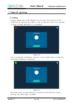
Страница 43: ...he exoskeleton by looking at the indicator in the top left side of the screen red light on Figure 39 shows that there is no connection Figure 39 Turn on exoskeleton and wait for connection to be set green light on Figure 40 shows that exoskeleton is connected Figure 40 Input login doctor and password doctor and then press Authorization button Currently only default login is available ...

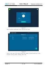
Страница 44: ... ExoAtletⓇ II 43 84 Ver 1 0 2019 03 29 Figure 41 After successful authorization main menu will be shown Figure 42 Press on the logo in the top left side of the screen You will see the list of the sections Training Service Settings About Exit ...

Страница 45: ...2 Trainings Figure 44 In the Trainings section you can open all the finished training and see the basic information about it more details in 8 2 2 You can exit training by pressing arrow button in the top left side of the screen See Figure 45 and then you will return to the Trainings screen ...

Страница 46: ...ser s Manual http www exoatletasia com ExoAtletⓇ II 45 84 Ver 1 0 2019 03 29 Figure 45 7 2 1 Starting training Press button in the bottom right side of the screen to create new training session Figure 46 ...

Страница 47: ... blood pressure saturation by pressing the buttons with arrow in the right side from the value Then press OK You will get to the training screen Warning please pay attention that device does not measure these values by itself User should measure them using appropriate equipment and then type them Warning there is a range of the values that you can enter If one of the vital values of the patient ex...

Страница 48: ...d statistics of the training Training consists of the motion buttons different settings buttons and remote control switch Events shows the log of the events that were performed during training Before pressing Start training button all the buttons are unavailable Press Start training to start training session and get access to the motion buttons Figure 49 After pressing Start training button main b...

Страница 49: ...ult in incorrect walking and even injury of the patient because exoskeleton calculates the walking pattern according to these values 2 Stop training After training you should press Stop training button After pressing it will be proposed to enter current values of pulse blood pressure and saturation again Figure 51 Also you may leave a comment for the training more details in 8 2 2 6 Then you shoul...

Страница 50: ...e current pose of the exoskeleton There are 3 available poses Undefined pose when limbs of the exoskeleton are not in standard sitting or standing pose If you moved some of the limbs before turning on exoskeleton it will probably be in this pose In this pose only Pose reset more details in 8 2 2 3 5 motion is available see Figure 53 Figure 53 ...

Страница 51: ...mbs of the exoskeleton are in standard standing position In this pose motions Sit down more details in 8 2 2 3 1 Walking in place more details in 8 2 2 3 4 Walking more details in 8 2 2 3 3 and Pose reset more details in 8 2 2 3 5 are available see Figure 55 Figure 55 Warning before pressing any motion button you have to check the selected motion parameters more details in 8 2 4 to react properly ...

Страница 52: ...will bend its legs first left then right and then the Confirm action window will appear see Figure 56 Only after pressing OK button and after 3 beeps standing up will be initiated and exoskeleton will get into standing position When finished it will beep one more time to show that device is ready for the next motion Figure 56 If you will press Cancel exoskeleton may get into undetermined pose or s...

Страница 53: ...o choose the desired pose you want to transfer exoskeleton to see Figure 57 After pressing Reset exoskeleton will perform 3 beeping sounds and then will slowly get to the desired position When finished it will beep one more time to show that device is ready for the next motion Figure 57 4 Remote control mode Switching to Remote control mode will allow control from remote control on the crutch More...

Страница 54: ...u will press on one of the events in Events section you will open Notes window It will be possible to choose the type of the note for this event Technical Wishes Exercises Settings Other After typing the comment and then pressing Save button the note will be saved and the symbol according to the type of the note near the chosen event will appear it shows that there is a note for this exact event P...

Страница 55: ...iate motions of the exoskeleton Press Save button in top right side of the screen to save current parameters Press back arrow in the top left side of the screen to close settings screen without keeping the changes Warning you should carefully check that shank length and thigh length in the settings are similar to the ones that set on exoskeleton Otherwise it may result in incorrect walking and eve...

Страница 56: ...Hip width min 320 max 460 step 1 0 12 Hip abduction adduction min 3 max 4 step 1 13 Back height min 160 max 190 step 5 14 Pad under the belly S M L 15 Pad under the back S M L 16 Straps position for upper position of the straps for lower position of the straps 17 Buttock belt length min 0 max 15 step 1 18 Height of the crutches min 1 max 10 step 1 19 Height of the bars min 1 max 7 step 1 Warning t...

Страница 57: ... access to the parameters of walking See Figure 62 Figure 62 Press Back button in top left side of the screen to leave the settings without any changes You can adjust various parameters Pause between steps parameter defines the time between ending one step and starting another step available only in Continuous mode Min 0 max 1 s step 0 1 s ...

Страница 58: ...rned on it activates a short beeping sound before every step of exoskeleton It helps some patients to understand when exactly the step will start Additional effort of the exoskeleton when the button is pressed Additional effort screen will appear see Figure 63 It is possible to define the degree of support from the exoskeleton on every limb from 5 minimal assistance exoskeleton almost doesn t help...

Страница 59: ...m the left leg Motion stop button will appear on the screen also M indicator will appear on the top right side of Training section showing that exoskeleton is currently in motion You will be able to see the chosen mode in the bottom side of Training section see Figure 65 Exoskeleton can be stopped using stop button on Tablet PC or stop button on the left handle After pressing one of the stop butto...

Страница 60: ...ignals in case of Sound indication is not activated To stop walking and make a final step you should hold the button on the left handle and after 1 second exoskeleton will make a final step and get into standing pose After finished it will beep one more time to show that device is ready for the next motion If you will hold the button before making first step exoskeleton will immediately get into s...

Страница 61: ...utton on Tablet PC or button on the left handle After it patient will have to initiate one last step to get exoskeleton into standing pose After finished it will beep one more time to show that device is ready for the next motion If you will press stop button before first step exoskeleton will immediately return to standing pose waiting for the next motion Warning initiation by effort should be us...

Страница 62: ... of exoskeleton It helps some patients to understand when exactly the step will start Additional effort of the exoskeleton when the button is pressed Additional effort screen will appear see Figure 63 It is possible to define the degree of support from the exoskeleton on every limb from 5 minimal assistance exoskeleton almost doesn t help to perform movement to 100 maximal assistance exoskeleton m...

Страница 63: ...e several parameters to change See Figure 68 Figure 68 Standing up time parameter defines the time that exoskeleton will need to get from sitting to standing position Min 2 s max 5 s step 0 1 s Angle of knee bend parameters defines how much exoskeleton will bend its knees before standing up Min 80 deg max 100 deg step 2 deg Use minimal value in case of high stool and max value in case of the low s...

Страница 64: ...e of the movement settings all the changes will be kept and you will get back to the motion parameters screen You will see that motion was changed by an orange tag in the bottom side of the button see Figure 70 Pay attention that if you will change parameters of only one of the movements tag will appear only below the exact button Figure 70 ...

Страница 65: ... using Pose reset button If error will appear continuously you should remember the error code and contact technical support by the phone number displayed on the screen Warning check if the patient is not entrapped and there is no excessive pressure on the patient Check if the position of the patient is normal in the exoskeleton After that you can continue training Figure71 If case of unexpected di...

Страница 66: ...skeleton will start to create a backup file and it will take some time Figure 73 During creating of the backup file some errors may appear for example in case of lack of connection between Tablet PC and exoskeleton In that case you will see an error message on the screen You can try to create it again or leave without creating a file After successful creating of the backup file you will get an opt...

Страница 67: ...User s Manual http www exoatletasia com ExoAtletⓇ II 66 84 Ver 1 0 2019 03 29 Figure 74 7 4 Settings Settings section allows user to connect Tablet PC to a wi fi or change the language Figure 75 ...

Страница 68: ...tⓇ II 67 84 Ver 1 0 2019 03 29 7 5 About About section shows user the current version of the Tablet PC software This information may be helpful for a technical support Figure76 7 6 Exit Pressing Exit button will return user to the log screen see 8 1 ...

Страница 69: ... 2019 03 29 8 ExoCrutch operation 8 1 ExoCrutch structure ExoCrutch contains of 6 main components 8 1 1 Turn ON button 8 1 2 LED indicator 8 1 3 Charging port USB type C 8 1 4 Display 8 1 5 Mode change button 8 1 6 Action button Figure 77 Figure 78 Figure 79 Figure 80 ...

Страница 70: ...arge indicator Exoskeleton charge indicator Exoskeleton current condition indicator Selected motion mode Figure 81 8 2 ExoCrutch available motions Icon Value Not defined pose Pose reset to sitting pose Pose reset to standing pose Sitting pose Standing up Low Standing up Middle Standing up High Standing pose Sitting down ...

Страница 71: ...control operation using switch on the bottom side of the display more details in 8 2 2 4 3 Turn ExoCrutch on using Turn ON button on the front side of the device You will see that device is in the process of connecting to exoskeleton Figure 82 Walking in place high step Walking in place low step Walking short and high step Walking short and low step Walking middle and high step Walking middle and ...

Страница 72: ...PC you will see an error icon on the display after ExoCrutch initialization Figure 83 4 After successful initialization you will see a working screen Figure 84 8 4 ExoCrutch operation 8 4 1 Depending on the current pose you have different available motions see clause 9 2 for reference 8 4 2 Using Mode change button choose the desirable motion ...

Страница 73: ...firm motion only when you change the desirable motion If you walked and then pressed stop it is not necessary to confirm the motion again if you didn t change it 8 4 4 Press Action button to execute selected mode motion Warning it is possible to initiate only continuous mode with ExoCrutch more details on operation in 8 2 4 1 8 4 5 Press Action button again during walking to stop it Or just wait f...

Страница 74: ...utton to reset error Error signals will stop 8 5 2 Choose the desirable pose for exoskeleton to come to Press Action button and after 3 signals exoskeleton will get into the desirable pose Warning if an error appeared during walking you should choose Standing pose If an error appeared during standing up or sitting down you should choose Sitting pose Warning check if the patient is not entrapped an...

Страница 75: ...the battery 9 1 Charging exoskeleton 9 1 1 Connect the charger to the port on the right side of the exoskeleton Figure 88 9 1 2 Plug the charger into the outlet Lights will turn red on the chargerand exoskeleton and LED bar on the exoskeleton will show the current charge 1 bar 20 Figure 89 ...

Страница 76: ...den to charge exoskeleton with the patient inside the device 9 2 Charging Tablet PC 9 2 1 Tablet PC has a port on the bottom side so it charges from exoskeleton Figure 90 9 2 2 Connect Tablet PC to the charging port on the top of exoskeleton turn exoskeleton on The charging process will be shown on the display Figure 91 9 2 3 Tablet PC can be charged if exoskeleton is turned on or connected to the...

Страница 77: ...rutch 9 3 1 Connect the charger to the port on the front side of the device Figure 92 9 3 2 Plug the charger into the outlet Light will turn red on the front side of the device ExoCrutch is now charging Figure 93 9 3 3 When charging is finished light will turn green so you can unplug the charger ...

Страница 78: ...e battery is not charged please charge the battery If it doesn t work even though it s charged please contact the place of purchase 10 2 When connecting Symptom Checklist Solution method When communication with the body does not connect Turn on the main body and beep when the boot is complete Please check if the beeper sounds normal When the beeper sounds please exit and re run the application on ...

Страница 79: ...ke a noise during operation The motor may make a noise during operation When motion is stopped due to stiffness during operation If the pilot s body is subject to stiffness the sensor may stop working Please check the pilot s condition Press Error Correction and then press Posture to sit the pilot on the chair Please check the status of your pilot When the power is turned off during operation Plea...

Страница 80: ...ustomer service center for action If you need to replace the corset and strap for fixing your body you can buy it again through the manufacturer Do not disassemble or disassemble the unit All information about the repair and replacement of the equipment circuit diagram wiring diagram parts replacement method etc is provided to our A S team and should be performed by the personnel designated by us ...

Страница 81: ...f this device is in reasonable control Manufacturer ExoAtlet Asia Co Ltd Head office 212 Janghang ro 225beon gil Ilsandong gu Goyang si Gyeonggi do Korea Factory 2F Happyland Annex 66 Digital ro 31 gil Guro gu Seoul Korea Tel 82 2 2051 1596 Fax 82 2 2051 1594 Homepage http www exoatletasia com The company homepage of ExoAtlet Asia Co Ltd can be used effectively to notify the customer of complaints...

Страница 82: ...s suitable for use in all establishments other than domestic and may be used in domestic establishments and those directly connected to the public low voltage power supply network that supplies buildings used for domestic purposes provided the following warning is heeded Warning This equipment system is intended for use by professionals only This equipment system may cause radio interference or ma...

Страница 83: ...ality should be that of a typical commercial or hospital environment Voltage dips short interruptions and voltage variations on power supply input lines EN 61000 4 11 5 UT 95 dip in UT for 0 5 cycle 40 UT 60 dip in UT for 5 cycles 70 UT 30 dip in UT for 25 cycles 5 UT 95 dip in UT for 5 s 5 UT 95 dip in UT for 0 5 cycle 40 UT 60 dip in UT for 5 cycles 70 UT 30 dip in UT for 25 cycles 5 UT 95 dip i...

Страница 84: ...e in metres m Field strengths from fixed RF transmitters as determined by an electromagnetic site survey a should be less than the compliance level in each frequency range b Interference may occur in the vicinity of equipment marked with the following symbol NOTE 1 At 80 MHz and 800 MHz the higher frequency range applies NOTE 2 These guidelines may not apply in all situations Electromagnetic propa...

Страница 85: ...mum output power of the communications equipment Rated maximum output power of transmitter W Separation distance according to frequency of transmitter m 150 kHz to 80 MHz d 1 17 80 MHz to 800 MHz d 1 17 800 MHz to 2 5 GHz d 2 33 0 01 0 117 0 117 0 233 0 1 0 370 0 370 0 736 1 1 17 1 17 2 33 10 3 70 3 70 7 36 100 11 7 11 7 23 3 For transmitters rated at a maximum output power not listed above the re...

Страница 86: ... be determined by turning the equipment off and on the user is encouraged to try to correct the interference by one of the following measures Reorient or relocate the receiving antenna Increase the separation between the equipment and receiver Connect the equipment into an outlet on a circuit different from that to which the receiver is con nected Consult the dealer or an experienced radio TV tech...

Отзывы: