background image


- 22 - 


4.1.9   

Check tire pressures. 


Service Interval:


Pneumatic (air-filled) Drive Tires-


40 hrs.     


Semi-pneumatic Caster Tires – No maintenance


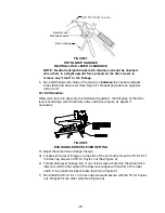
a)  Stop engine and wait for all moving parts to stop.  Remove spark plug wire(s).  

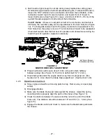
Check air pressure in drive tires; recommended tire pressure is: 12 to 16 psi 
(83-110 kPa).  


b)  Inflate tires to pressures stated above.  Measure the circumference of each 

drive tire.  Adjust tire pressures within the above range to try to make tire 
circumferences match as closely as possible. 


4.1.10  

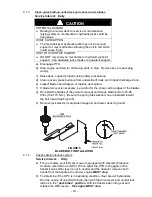
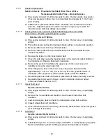
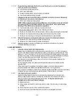
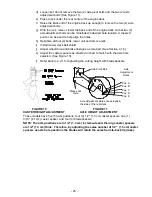
Check grease level, input and output shaft bearing wear on Peerless 
Transmission.  (Replace gearbox grease yearly) 


Service Interval: 160 hrs.


a)  Stop engine and wait for all moving parts to stop.  Remove key or spark plug 

wire(s).   


b)  Place drive levers and neutral lock/park brake latches in neutral lock position. 


c)  Remove shifter lever from top of transmission. 


d)  Remove shifter plate from top of transmission and the two leads from the 

neutral start switch. 


e)  Release the tension on the transmission belt. 


f)  Check for side play caused by bearing wear on the input and output shafts of 

the transmission. Replace bearings if necessary. 


g)  Remove the six bolts that fasten the upper case to the lower case and 

carefully remove the upper case half. 


h)  Check the grease level in the lower case. The grease level should be 

approximately 1-1/2" to 1-3/4" (3.8 to 4.4 cm) from the gearbox bottom. If 
necessary, fill to proper level with Peerless grease (Part No. 788067). 


I)  Reinstall upper case half and fasten in place with six bolts previously removed. 


j)  Reinstall all parts removed in Steps c and d. Install drive belt and adjust 

tension as stated in Section 4.2.3. 


4.1.11   

Inspect belt wear. 


Service Interval: 40 hrs.


a)  Stop engine and wait for all moving parts to stop.  Remove key or spark plug 

wire(s).   


b)  Remove the mower deck belt shield to check mower blade drive belt 

condition. 


c)  Look under engine deck to check the transmission drive belt condition. 


d)  Inspect wheel drive belt conditions. 


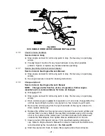
e)  Check all idler arms to be sure they pivot freely. Disassemble, clean and grease 

pivot bushings if necessary. 

 4.1.12 


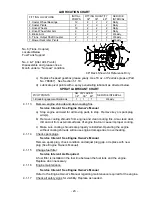
Lubrication: 


Service Interval: Refer to Chart


a)  Stop engine and wait for all moving parts to stop.  Remove key or spark plug 

wire(s).   


b)  Lubricate fittings with one to two pumps of SAE No. 2 multi-purpose gun grease

.  

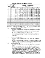
Refer to the following chart for fitting locations and lubrication schedule. 


Содержание Lazer ZXS

Страница 1: ...For Serial Nos 600 000 Higher Part No 103 9911 Rev A ...

Страница 2: ...rom eyes and skin Never siphon by mouth IMPORTANT When the mower is used or operated on any California forest brush or grass covered land a working spark arrester must be attached to the muffler If not the operator is violating state law Section 4442 Public Resource Code To acquire a spark arrester for your unit see your Engine Service Dealer This spark ignition system complies with Canadian ICES ...

Страница 3: ...bmitting the Exmark Parts Plus order to Exmark by 3 00 p m central time the Distributor pays for the part and freight 3 Exmark being unable to ship the part and the Exmark parts order is received by 3 00 p m central time Exmark pays for the part and freight 4 If the part does not arrive overnight due to the shipper UPS the shipper pays for the freight and Exmark pays for the part The following res...

Страница 4: ...wer maintain its maximum efficiency and promote safe operation If additional information is needed or should you require trained mechanic service contact your authorized Exmark equipment dealer or distributor All Exmark equipment dealers and distributors are kept informed of the latest methods of servicing and are equipped to provide prompt and efficient service in the field or at their service st...

Страница 5: ...9 2 9 Deck 9 10 2 10 Dimensions 10 2 11 Bolt Torque Requirements 10 3 OPERATION INSTRUCTIONS 3 1 Controls 10 12 3 2 Pre Start 12 3 3 Operating Instructions 13 16 3 4 Transporting 16 4 MAINTENANCE ADJUSTMENTS 4 1 Periodic Maintenance 17 24 4 2 Adjustments 24 30 5 WASTE DISPOSAL 5 1 Motor Oil Disposal 30 6 TROUBLE SHOOTING 6 1 Mower Tracks Left or Right 30 31 6 2 Mower Cuts Unevenly 31 6 3 Blades Do...

Страница 6: ...erator s or mechanic s can not read English it is the owner s responsibility to explain this material to them 1 2 3 Do not allow operation of this machine by untrained personnel Never allow children teenagers or people unfamiliar with these instructions to use the mower Local regulations may restrict the age of the operator 1 2 4 Avoid mowing while people especially children or pets are nearby Kee...

Страница 7: ... burn you others and cause property damage HOW TO AVOID THE HAZARD DO NOT smoke while refueling and stay away from an open flame or where gasoline fumes may be ignited by spark Refuel only outdoors Store gasoline in an approved container and keep it out of the reach of children Add fuel before starting the engine Never remove the cap of the fuel tank or add fuel when engine is running or when the ...

Страница 8: ...tank or container opening at all times until fueling is complete WARNING POTENTIAL HAZARD Gasoline vapor can collect inside enclosed trailers and may be ignited by electrical sparks or hot engine exhaust components WHAT CAN HAPPEN Explosion and fire may occur resulting in property damage personal injury and or death HOW TO AVOID THE HAZARD Provide adequate ventilation of any enclosed trailer to pr...

Страница 9: ...ing away from rotating parts 1 4 1 Give complete undivided attention to the job at hand 1 4 2 Mow only in daylight or in good artificial light keeping away from holes or hidden hazards DO NOT operate the mower when children or others are in the area 1 4 3 When feasible avoid operating the equipment in wet grass 1 4 4 Use EXTREME caution when mowing and or turning on slopes as loss of traction and ...

Страница 10: ...d in proper working condition 1 4 8 Do Not change the engine governor settings or overspeed the engine Operating an engine at excessive speed may increase the hazard of personal injury 1 4 9 Place transmission in neutral disengage PTO and latch drive levers in park brake position before starting engine 1 4 10 Start the engine carefully with feet well away from the blades 1 4 11 Keep hands feet and...

Страница 11: ...en pilot lights or heat appliances are present 1 5 6 Maximum mowing results and safety can only be achieved if the mower is properly maintained and operated correctly 1 5 7 Check all bolts frequently to maintain proper tightness 1 5 8 Keep all guards shields and all safety devices in place and in safe working condition 1 5 9 Frequently check for worn or damaged components that could create a hazar...

Страница 12: ...ION Right Rear Corner of Deck PART NO 1 303517 LOCATION Left Side Rear Surface Engine Deck PART NO 103 1798 LOCATION RH Side of Console PART NO 1 323427 LOCATION 32 36 Decks Under Belt Shield PART NO 103 5626 LOCATION 48 Decks Under Belt Shield PART NO 98 5954 LOCATION Under Mower Deck Belt Shield ECS Handle Units PART NO 103 2244 LOCATION LH Side of Console ECS Handle Units PART NO 103 2245 LOCAT...

Страница 13: ...le Units PART NO 1 323550 LOCATION Upper Handles Both Sides PART NO 1 403143 LOCATION Right Rear of Engine Deck ECS Handle Units PART NO 103 1623 LOCATION Console Pistol Grip Handle Units PART NO 103 1967 LOCATION Console ...

Страница 14: ...endent control of traction braking and neutral to each drive wheel for moving stopping and power turning Parking brakes are engaged by locking drive control levers in the brake position 2 6 TRANSMISSION 2 6 1 Peerless 700 070A five speeds forward and one reverse 2 6 2 Speed range 1st 2 0 mph 3 22 km h 4th 4 1 mph 6 60 km h 2nd 2 7 mph 4 35 km h 5th 6 2 mph 9 98 km h 3rd 3 5 mph 5 63 km h Rev 3 1 m...

Страница 15: ...es 420 lbs 191 kg 430 lbs 195 kg 475 lbs 215 kg ECS Handles 435 lbs 197 kg 446 lbs 202 kg 490 lbs 222 kg Weights will vary slightly depending on engine option 2 10 4 Tread Width 32 36 48 Standard Pistol Grip ECS Handles 32 1 in 81 4 cm 35 6 in 90 4 cm 35 6 in 90 4 cm To outside of tires 2 10 5 Overall Height Standard Pistol Grip Handles 40 0 in 101 6 cm ECS Handles 42 1 in 106 9 cm 2 11 TORQUE REQ...

Страница 16: ...ow down until they reach neutral or stop This makes the machine urn to the left or right respectively Squeezing further engages the park brakes The sharpness of the turn varies by how much the lever is squeezed For straight ahead motion smoothly release both drive levers to engage both drive wheels simultaneously 3 1 4 Neutral Lock Park Brake Latches The latches allow the operator to lock the driv...

Страница 17: ...e Shift transmission only when drive levers are in the neutral position Shifting without drive levers in neutral may cause damage to the transmission NOTE Reverse is reverse assist only meaning when the transmission is in reverse the operator has to pull the unit backward to assist with the movement of the unit 3 1 10 Fuel Shut Off Valve Installed on the fuel line midway between the fuel tank and ...

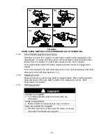
Страница 18: ... the Off position Close fuel shut off valve if machine will not be used for a few days when parking inside a building or when transporting the unit 3 3 4 Drive Lever Neutral Lock Park Brake Latch Operation For Pistol Grip Handles To lock the drive levers in neutral squeeze the drive levers back to the neutral position Place thumbs on the upper portion of the neutral lock park brake latches and mov...

Страница 19: ...e levers could unexpectedly slip into the forward drive position WHAT CAN HAPPEN If the drive levers slip into the drive position the unit could lurch forward and cause injury or property damage HOW TO AVOID THE HAZARD Be sure the drive levers are securely seated at the bottom of the neutral or park areas of the neutral lock latches To place the drive levers in the drive position slightly squeeze ...

Страница 20: ...eels For turning Squeeze the right hand drive lever to turn right and squeeze left hand drive lever to turn left See Section 3 1 3 3 3 6 Stopping the Unit Squeeze drive levers all the way back to engage brakes Move neutral lock park brake latches into the park brake position and release drive levers Shift transmission into neutral 3 3 7 PTO Engagement DANGER POTENTIAL HAZARD The rotating blades un...

Страница 21: ...h a knee or by hand engage the neutral lock latches if shifting by hand NOTE Reverse gear is reverse assist only the operator must pull the unit backwards 3 4 TRANSPORTING WARNING POTENTIAL HAZARD Loading the mower onto a trailer without strong enough or properly supported ramps could be dangerous WHAT CAN HAPPEN The ramps could collapse causing the unit to fall which could cause injury HOW TO AVO...

Страница 22: ...ng repairs around the engine area 4 1 1 Check engine oil level Service Interval See Engine Owner s Manual a Stop engine and wait for all moving parts to stop Make sure machine is on a level surface b Check with engine cold c Clean area around dipstick Remove dip stick and wipe off oil Reinsert the dipstick Do not screw into place Remove dipstick and check oil level d If the oil level is low add oi...

Страница 23: ...ce as required f If blade removal is necessary be careful for the sharp cutting edges of the blades g Re install the blades if they were removed and torque blade bolts to 75 85 ft lbs 102 115 N m Be sure the spring disk washer cone is installed toward the bolt head See Figure 5 h Remove jack stands or equivalent support and lower deck to ground FIGURE 5 BLADE BOLT INSTALLATION 4 1 4 Check safety i...

Страница 24: ...are squeezed enough to allow the neutral lock park brake latches to be placed into the park brake position See Figure 3 for Standard Pistol Grip handles and Figure 4 for ECS handles NOTE The neutral lock park brake latches must be able to be moved into the park brake position if not the brake linkages must be adjusted again c Check for correct wheel drive linkage adjustment For Pistol Grip Handles...

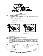
Страница 25: ...o the full forward position the flat edge of the drive lever should align with the bottom roller notch See Figure 8 Adjust if necessary FIGURE 8 ECS HANDLE DRIVE LEVER SETTING To adjust the wheel drive linkage linkage d Locate a drive lever linkage on one side of the unit and remove the 5 16 18 x 1 3 4 Hex cap screw and 5 16 18 nyloc nut See Figure 9 e Thread drive lever linkage into or out of the...

Страница 26: ... PTO b Stop engine and wait for all moving parts to stop Remove key or spark plug wire s c Drain oil while engine is warm from operation or if oil is to be changed after the unit has been sitting for awhile run engine for a few minutes to get it warm d Remove the oil drain plug from the right hand side of the engine Allow oil to drain replace drain plug e Replace the oil filter per the engine owne...

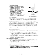
Страница 27: ... transmission Replace bearings if necessary g Remove the six bolts that fasten the upper case to the lower case and carefully remove the upper case half h Check the grease level in the lower case The grease level should be approximately 1 1 2 to 1 3 4 3 8 to 4 4 cm from the gearbox bottom If necessary fill to proper level with Peerless grease Part No 788067 I Reinstall upper case half and fasten i...

Страница 28: ...1 13 Remove engine shrouds and clean cooling fins Service Interval See Engine Owner s Manual a Stop engine and wait for all moving parts to stop Remove key or spark plug wire s b Remove cooling shrouds from engine and clean cooling fins Also clean dust dirt and oil from external surfaces of engine that can cause improper cooling c Make sure cooling shrouds are properly reinstalled Operating the en...

Страница 29: ...djusting cutting height with blade spacers Blades may be adjusted for cutting height by using the four 1 4 64 cm spacers found on the blade spindle bolts factory setting is two above and two below This allows a 1 2 5 cm range in 1 4 64 cm increments of cutting height in any axle position The same number of blade spacers must be used on all blades to achieve a level cut two above and two below one ...

Страница 30: ...ee Section 4 1 5 k Adjust the caster spacers as directed in chart to match with the axle hole selected See Figure 10 l Refer back to 4 2 1 for adjusting the cutting height with blade spacers FIGURE 10 FIGURE 11 CASTER HEIGHT ADJUSTMENT AXLE HEIGHT ADJUSTMENT These models have five 5 axle positions four 4 1 2 1 3 cm caster spacers one 1 3 16 47 cm caster spacer and four 4 blade spacers NOTE The axl...

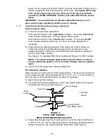
Страница 31: ...ve the highest quality of cut the blades should be level with the ground or tipped slightly down at the front 4 2 3 Transmission belt adjustment a Stop engine and wait for all moving parts to stop Remove key or spark plug wire s b To tighten transmission belt loosen the 3 8 nyloc nut on transmission belt idler pulley Slide bolt inward in slot and retighten nyloc nut c When properly adjusted the be...

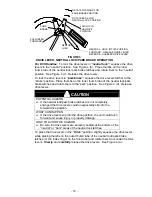
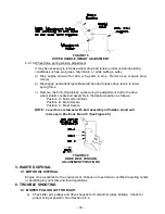
Страница 32: ...er the first hour of operation and at least twice during the first 24 hours of operation Adjust as necessary FIGURE 12 MOWER DECK BELT ADJUSTMENT d Proper belt tension will require about 10 lbs side pull on belt halfway between pulleys See Figure 12 Point A to deflect belt 1 2 12 mm e Check belt guide under the engine deck to see that it is properly set See Section 3 2 7 Also check the blade brake...

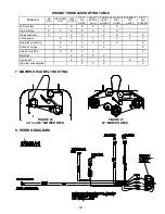
Страница 33: ... NOTE These drawings are viewed from underneath the engine deck FIGURE 14 FIGURE 15 32 36 BELT GUIDE LOCATION 48 BELT GUIDE LOCATION 4 2 8 Brake adjustment See Section 4 1 5 4 2 9 Wheel drive linkage adjustment See Section 4 1 5 4 2 10 Shifter lever adjustment The shifter lever in neutral should not contact the upper or lower edge of the slot or the left edge of the upper slot or the right edge of...

Страница 34: ...t gears Turn setscrew out counterclockwise to decrease force on lever required to shift gears Factory setting is to turn setscrew all the way in then back out 1 1 2 turns IMPORTANT Screwing setscrew in too far will prevent the transmission from shifting 4 2 12 PTO safety switch adjustment a Stop engine and wait for all moving parts to stop Remove key or spark plug wire s b With the blades disengag...

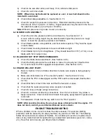
Страница 35: ...o the drive wheel shield Locate bolt assembly in the desired position as follows Position A Normal Conditions Position B More Severe Position C Most Severe NOTE Lever force is lowest with bolt assembly in Position A and will increase in Positions B and C See Figure 20 FIGURE 20 DRIVE BELT TENSION ADJUSTMENT POSITIONS 5 WASTE DISPOSAL 5 1 MOTOR OIL DISPOSAL Engine oil is a pollutant to the environm...

Страница 36: ...r deck to make it is properly set See Section 5 2 7 and check the PTO engagement adjustment See Section 4 2 5 6 4 ENGINE WILL NOT START a Refer to Section 4 3 2 and follow directions to make sure engine is being properly choked b Make sure transmission is in true neutral position See Sections 3 12 c c Check that the PTO is disengaged and the PTO switch is depressed See Section 4 2 12 d Check that ...

Страница 37: ... AIR SCREEN Will not start X X X X X X Hard starting X X X X X X X Stops suddenly X X X X X X X Lacks power X X X X X X X X Operates erratically X X X X X X X Knocks or pings X X X X Skips or misfires X X X X X Backfires X X X X Overheats X X X X X High fuel consumption X X X X 7 MOWER DECK BELT ROUTING FIGURE 26 FIGURE 27 32 and 36 MOWER DECK 48 MOWER DECK 8 WIRING DIAGRAM ...

Страница 38: ...sfied with the Service Dealer s analysis or with the assistance provided contact us at Exmark Customer Service Department The Exmark Warranty Company 2101 Ashland Avenue Beatrice NE 68310 402 223 6375 or service exmark com Owner s Responsibilities The Exmark turf equipment including any defective part must be returned to an authorized Exmark service dealer within the warranty period This warranty ...

Страница 39: ...t as required maintenance in the written instructions must be warranted for the warranty period of two years If any such part fails during the period of warranty coverage it must be repaired or replaced by Exmark Manufacturing Company Any such part repaired or replaced under the warranty must be warranted for a time not less than the remaining warranty period B Any warranted part that is scheduled...

Страница 40: ... 35 NOTES ...

Страница 41: ... 36 NOTES ...

Страница 42: ... 37 SERVICE RECORD Date Description of Work Done Service Done By ...

Страница 43: ...L O P E T H IS IS A 1 0 S L O P E T H IS IS A 5 S L O P E ALIGN THIS EDGE WITH A VERTICAL SURFACE TREE BUILDING FENCE POST POLE ETC EXAMPLE COMPARE SLOPE WITH FOLDED EDGE FOLD ALONG APPROPRIATE LINE T H I S I S A 2 0 S L O P E ...

Страница 44: ...AC QUICK DISPOSAL SYSTEM WALK BEHIND ACCESSORIES GRASS CATCHER MICRO MULCH SYSTEM STEERABLE SULKY SULKY HITCH KIT TURF STRIPER STANDON WARNING The engine exhaust from this product contains chemicals known to the State of California to cause cancer birth defects or other reproductive harm 1997 2005 EXMARK MFG CO INC PART NO 103 9911 Rev A INDUSTRIAL PARK BOX 808 402 223 6300 BEATRICE NE 68310 FAX 4...

Отзывы: