Maintenance
Spring Compression Distance Chart
Distance
Side Discharge Units—
Cut Height 2 inches or
above
13 1/2 inches (34.3 cm)
Side Discharge Units—
Cut Height below 2 inches
14 inches (35.6 cm)
60 Inch Rear Discharge
Units
10 1/2 inches (26.7 cm)
72 Inch Rear Discharge
Units
11 1/2 inches (29.2 cm)
Note:
When above adjustments have been made,
the front of the deck will be slightly lower than the
rear of the deck.
Pump Drive Belt Tension
Self-tensioning - No adjustment necessary.
Deck Belt Tension
Self-tensioning - No adjustment necessary.
Mule Drive Belt Tension
Adjustment
Service Interval: After the first 5 hours
Every 40 hours thereafter
Self-tensioning idler, adjust as follows:
1. Stop engine, wait for all moving parts to stop, and
remove key. Engage parking brake.
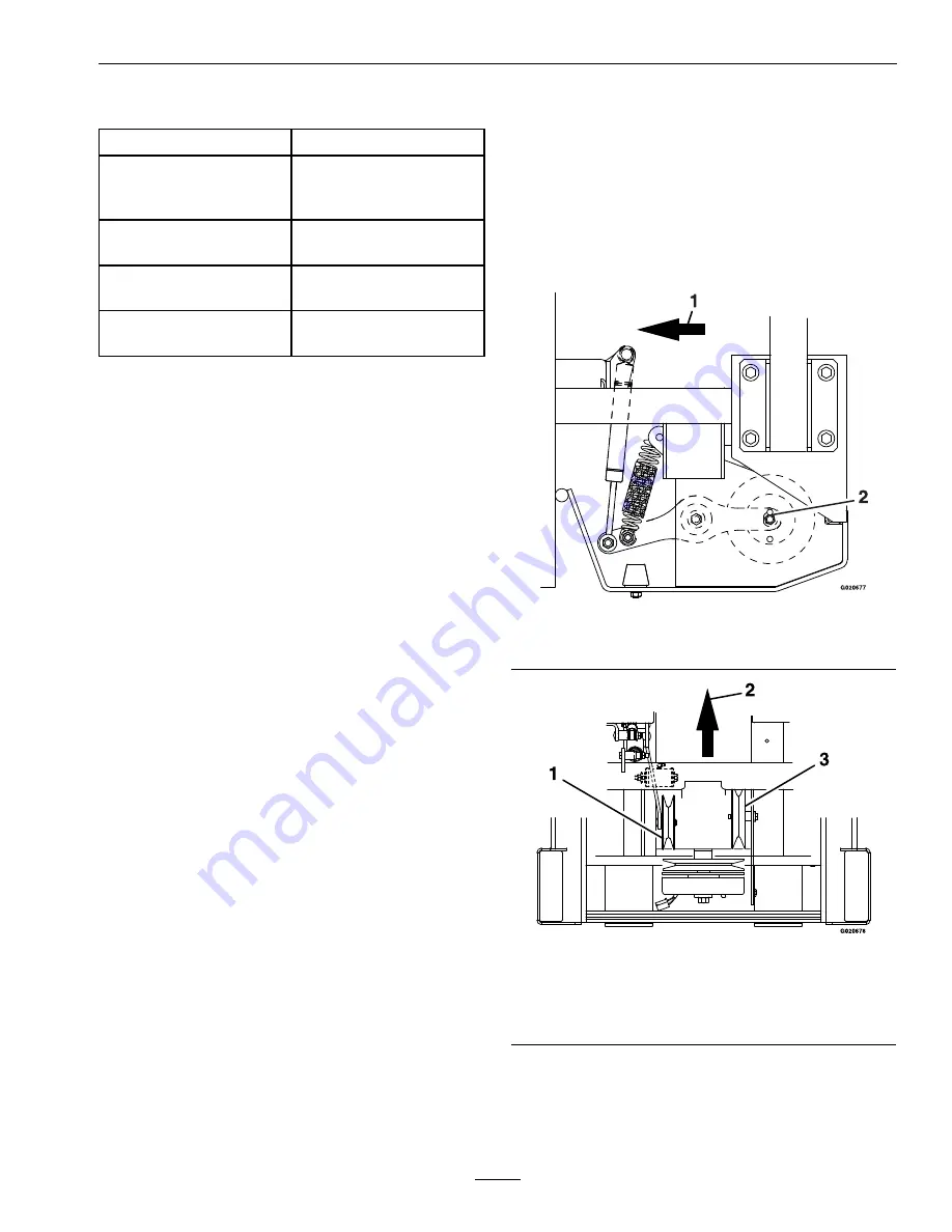
2. Check to make sure the center of the bolt head
in the center of the spring loaded pulley, on left
side engine deck support, is positioned between
the centers of the two alignment slots in the left
support plate (Figure 24 and Figure 25). It is
necessary to adjust the belt tension when the
center of the bolt head is at or below the center of
the bottom alignment hole.
3. When adjustment is necessary, loosen the idler
pulley on the right-hand side so it can move up
and down in the slot.
Place a wrench on the 3/8 inch nut in the center
of the spring loaded pulley and apply upward
pressure to relieve tension on the spring (a 1/2
inch drive breaker bar and 9/16 inch socket works
best).
Reposition the adjusting pulley towards the
bottom of the slot.
Note:
When installing a new belt, it is necessary
to reposition the right adjusting pulley upward in
the slot in order to position the center of the spring
loaded pulley between the alignment slots.
Figure 24
1.
Front of unit
2.
Alignment slots
Figure 25
1.
Spring idler pulley
2.
Front of unit
3.
Right side idler pulley (adjustable)
Note:
On Rear Discharge Units Only: If there is not
enough adjustment in the RH idler pulley to position
the spring idler pulley correctly, see
Secondary Mule
Belt Drive Tension Adjustment
section.
47
Содержание LAZER Z DS Series
Страница 1: ...LAZER Z DS SERIES For Serial Nos 400 000 000 Higher Part No 4503 187 Rev B ...
Страница 59: ...Schematics Schematics Electrical Diagram 59 ...
Страница 60: ...Schematics Electrical Schematic 60 ...
Страница 62: ...62 ...


