Maintenance
Adjustments
Note:
Disengage PTO, shut off engine, wait for
all moving parts to stop, engage parking brake, and
remove key before servicing, cleaning, or making any
adjustments to the unit.
CAUTION
Raising the mower deck for service or
maintenance relying solely on mechanical
or hydraulic jacks could be dangerous. The
mechanical or hydraulic jacks may not be enough
support or may malfunction allowing the unit to
fall, which could cause injury.
Do Not rely solely on mechanical or hydraulic
jacks for support. Use adequate jack stands or
equivalent support.
Deck Leveling
1. Position the mower on a flat surface.
2. Stop engine, wait for all moving parts to stop, and
remove key. Engage parking brake.
3. Check the tire pressure in the drive tires. Proper
inflation pressure for tires is 13 psi (90 kPa).
Adjust if necessary.
4. Position the transport lock in the latching
position.
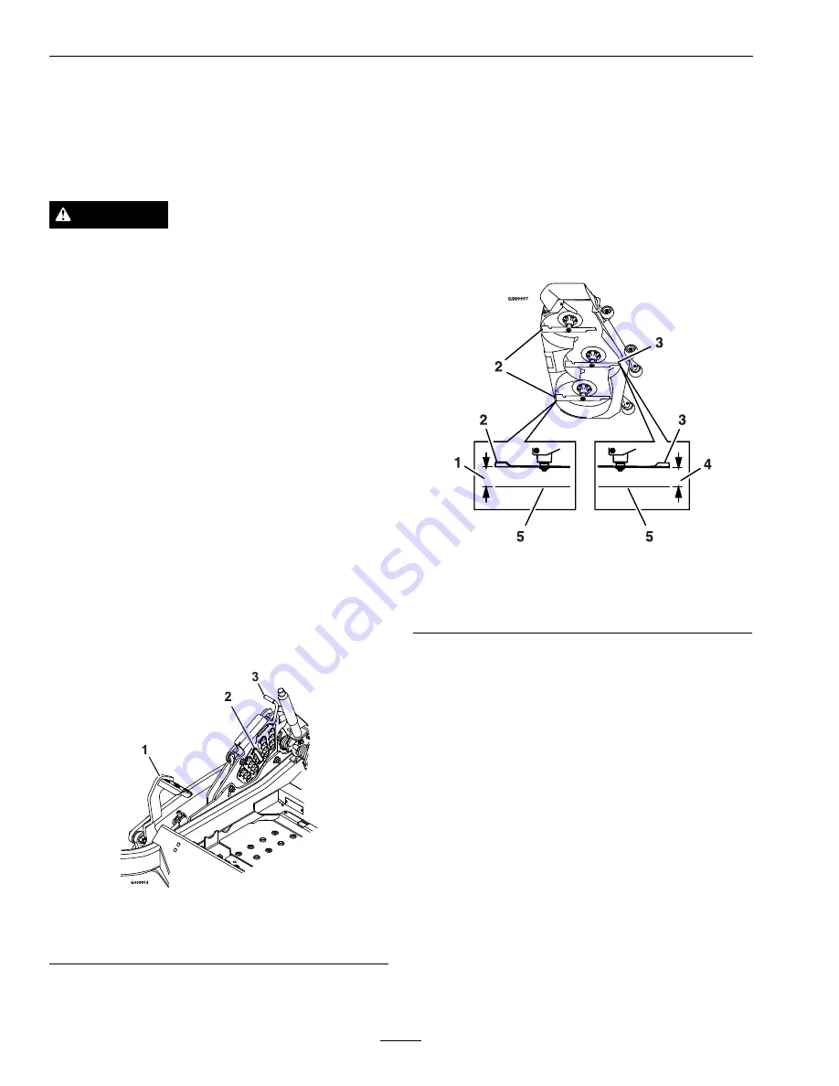
5. Push the foot pedal all the way forward and the
deck will latch at the 5 1/2 inch (14 cm) transport
position (Figure 27).
Figure 27
1.
Foot lever
3.
Transport lock
2.
Height of cut pin
6. Insert the height adjustment pin into the 3 inch
(7.6 cm) cutting height location.
7. Release the transport lock and allow the deck to
lower to the cutting height.
8. Raise the discharge deflector.
9. Measure from the level surface to the front tip of
the center blade. The measurement should read
3 inches (7.6 mm).
Note:
In most conditions, the back tips on the
side blades should be adjusted 1/4 inch (6.4 mm)
higher than the front.
Figure 28
1.
3 1/4 inches (8.3 cm)
4.
3 inches (7.6 cm)
2.
Back blade tip
5.
Level surface
3.
Front blade tip
10. For LZX-LP Units: Loosen the jam nuts on the
top of each deck link. Fine tune the adjuster on
the front deck lift assembly by turning it to get 3
inch (7.6 mm) height (see Figure 29).
To increase the height, turn the adjuster clockwise;
to decrease, turn counterclockwise.
42
Содержание Laser Z LZS29PKA604
Страница 1: ...LAZER Z PROPANE For Serial Nos 920 000 Higher Part No 4500 720 Rev A ...
Страница 14: ...Safety 109 9875 116 0157 1 See Operator s Manual 116 0205 116 0211 116 0752 1 Latch 2 Unlatch 14 ...
Страница 16: ...Safety 109 9906 16 ...
Страница 57: ...Schematics Hydraulic Diagram 57 ...
Страница 59: ...Notes 59 ...
Страница 60: ...Notes 60 ...
Страница 61: ...Service Record Date Description of Work Done Service Done By 61 ...
Страница 62: ...62 ...


