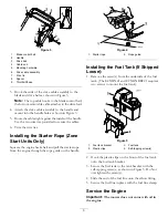
Removing the Unit from the Box
Remove the unit from the box.
Installing the Handle
1. Remove the mounting hardware from the mower
housing and handle bracket.
2. Lift the handle brackets upward and mount the
handle to the outside of the mower housing as
shown in Figure 1. Torque the handle mount screw
to 25 ft-lb (34 N-m).
G011039
1
2
1
4
3
5
Figure 1
1.
Handle bracket hardware
4.
Wire tie
2.
Handle bracket
5.
Handle mount screw
3.
Handle
Note:
The height of the handle can be adjusted for
comfortable operation. Stand behind the handle to
determine the height. To adjust the handle height,
position the hardware into one of the three holes in the
handle bracket.
Installing and Routing the
Cables-Except ECXHN21
1. Remove the drive/brake cable assembly mounting
hardware from the handle.
2. Route the cables of the drive/brake cable assembly
on the handle as shown in Figure 1 and Figure 2.
Figure 2
1.
Engine brake/blade control bail
2.
Handle
3.
Drive bail (Self-Propelled Units Only)
4.
Cable end
5.
Mounting hardware
6.
Drive/Brake cable assembly
7.
Wire tie
3. Hook the ends of the drive/brake cable assembly to
the blade and drive bails as shown in Figure 2.
Note:
The top cable hooks to the engine
brake/blade control bail; the bottom removable
cable attaches to the drive bail.
4. Attach the drive/brake cable assembly to the handle
and mount into the handle hole as shown in Figure 2.
Do Not overtighten.
5. Route the cables tight against the inside of the
handle. Use the two wire ties provided to secure the
cables tight against the handle.
6. Trim the wire ties.
Installing and Routing the Cables-
ECXHN21
1. Remove the drive cable assembly mounting hardware
from the handle.
2. Route the cables of the drive cable assembly on the
handle as shown in Figure 1 and Figure 3.
2


