background image

50-PIECE AIR TOOL KIT

1. Flush the tool with air-tool oil or gum 

    solvent.

2. Lubricate the tool.

3. a. Adjust the regulator on the tool to 

    maximum setting.

    b. Adjust the compressor regulator to tool 

    maximum of 90 PSI/6.3 BAR.

4. Tighten and seal hose fittings if leaks are 

    found. Use sealing tape.

5. a. Be sure the hose is the proper size. 

    Long hose or tools using large volumes 

    of air may require a hose with an I.D. of 

    1/2 in. or larger depending on the total

    length of the hoses.

    b. Do not use a multiple number of hoses 

    connected together with quick-connect 

    fittings. This causes additional pressure 

    drops and reduces the tool power. 

    Directly connect the hoses together.

6. Replace rotor blade.

7. Water in tank; drain tank. (See air 

    compressor manual). Oil tool and run 

    until no water is evident. Oil tool again 

    and run 1-2 seconds.

Tool runs 

slowly or will 

not operate

1. Grit or gum in tool.

2. No oil in tool.

3. Low air pressure.

4. Air hose leaks.

5. Pressure drops.

6. Worn rotor blade.

7. Moisture blowing 

    out of tool exhaust.                                                               

PROBLEM

TROUBLESHOOTING

                     CORRECTIVE ACTION

POSSIBLE CAUSE

CARE AND MAINTENANCE

An in-line oiler is recommended to be installed on air supply line as it increases tool 

life and keeps the tool in sustained operation. The in-line oiler should be regularly 

checked and filled with air-tool oil. Proper adjustment of the in-line oiler is performed 

by placing a sheet of paper next to the tool's exhaust ports and holding the throttle 

open approximately 30 seconds. The in-line oiler is properly set when a light stain of 

oil collects on the paper. Excessive amounts of oil should be avoided.

In the event that it becomes necessary to store the tool for an extended period of 

time, it should receive a generous amount of lubrication at that time. The tool should 

be run for approximately 30 seconds to ensure oil has been evenly distributed 

throughout the tool. The tool should be stored in a clean and dry environment.

Recommended lubricants: use air-tool oil or any other high-grade turbine oil 

containing moisture absorbent, rust inhibitors, metal wetting agents and an EP 

(extreme pressure) additive.

Clean the tool all over with a cotton rag after each use. Keep the tool in a dry and 

safe place out of reach of children.

23

Содержание EX5005KIT

Страница 1: ... Some dust created by using power tools contains chemicals known to the state of California to cause cancer and birth defects or other reproductive harm This product contains one or more chemicals known to the State of California to cause cancer and birth defects or other reproductive harm Wash hands after handling OPERATOR S MANUAL EX5005KIT 1 2 7 16 BITS HOLDER 3 8 TO 1 2 ADAPTOR EXTENSION BAR 1...

Страница 2: ... Wrench 11 3 8 Air Ratchet Wrench 13 Air Hammer 14 1 4 Air Die Grinder 16 OPERATION 19 1 2 Air Impact Wrench 19 3 8 Air Ratchet Wrench 20 Air Hammer 21 1 4 Air Die Grinder 21 TROUBLESHOOTING 23 CARE AND MAINTENACE 23 EXPLODED DIAGRAMS AND PARTS LISTS 24 1 2 Air Impact Wrench 24 3 8 Air Ratchet Wrench 25 Air Hammer 26 1 4 Air Die Grinder 27 WARRANTY 28 ...

Страница 3: ...d or under the influence of alcohol drugs or medication 2 Do not overreach Keep proper footing and balance at all times 3 Always wear eye protectors which provides protection from flying particles from the front and side when using the tool Ear protectors should also be worn 4 Never use oxygen carbon dioxide combustible gases or any other type of bottled gases as a power source for this tool 5 Alw...

Страница 4: ...op before putting it down after use 11 If necessary use clamps or proper devices to securely fix the workpiece when installing tightening or removing loosening threaded fasteners on the workpiece 12 For overhead work wear a safety helmet 13 Do not discard the safety instructions give them to the operator 14 Always store this product in a dry and safe place out of reach of children or untrained ope...

Страница 5: ... proper devices to securely fix the workpiece when installing tightening or removing loosening threaded fasteners on the workpiece 12 For overhead work wear a safety helmet 13 Do not discard the safety instructions give them to the operator 14 Always store this product in a dry and safe place out of reach of children or untrained operators Air hammer safety instructions 1 Always use the air hammer...

Страница 6: ... instructions give them to the operator 12 Always store this product in a dry and safe place out of reach of children or untrained operators WARNING Compressed air can be dangerous Ensure that you are familiar with all precautions relating to the use of compres sors and compressed air supply 1 Use only clean dry regulated compressed air as the power source 2 Make sure that the air compressor being...

Страница 7: ...ween air supply and hose whip 10 Check hoses for wear before each use Make certain that all connections are in security 6 Shut Off Valve 7 Whip Hose 8 Coupler Body And Connector 9 Drain Daily 10 1 2 Or Larger Pipe And Fitting AIR SYSTEM LAYOUT 1 Air Tool 2 Air Hose 3 8 I D 3 Oiler 4 Pressure Regulator 5 Filter 11 Air Dryer 12 1 Or Larger Pipe And Fitting 13 Air Compressor 14 Auto Drain 15 Drain Da...

Страница 8: ...ir Impact Wrench 3 8 Air Ratchet Wrench Air Hammer 1 4 Air Die Grinder Blow Gun Spring Retainer 3 Extension Bar 3 8 to 1 2 Adapter Bit Holder 1 2 Dr Impact Socket Chisel 50 psi Tire Gauge Dual Tire Chuck 1 1 1 1 1 1 1 1 1 6 2 1 1 A B C D E F G H I J K L M DESCRIPTION PART QUANTITY Screwdriver Bit Bit Base Grinding Stone Rubber Nozzle Tapered Nozzle Safety Nozzle Sports Needle Male Plug Female Plug...

Страница 9: ...h Air Inlet 1 1 1 1 1 A1 B1 C1 D1 E1 1 2 AIR IMPACT WRENCH 3 8 AIR RATCHET WRENCH DESCRIPTION QUANTITY PART 3 8 Air Ratchet Wrench Anvil F R Knob Trigger Air Regulator Exhaust Deflector Air Inlet Steel Ball Indicator 1 1 1 1 1 1 1 1 A2 B2 C2 D2 E2 F2 G2 H2 D1 E1 C2 F2 A2 H2 G2 E2 D2 B2 C1 B1 8 ...

Страница 10: ...t Jacket Collet Holder Collet Trigger Lever Air Regulator Exhaust Deflector Steel Ball Indicator Air Inlet 1 1 1 1 1 1 1 1 1 1 A4 B4 C4 D4 E4 F4 G4 H4 I4 J4 F4 E4 H4 I4 J4 G4 A4 C4 B4 D4 AIR HAMMER DESCRIPTION QUANTITY PART Air Hammer Air Inlet Trigger Cylinder 1 1 1 1 A3 B3 C3 D3 D3 A3 C3 B3 9 ...

Страница 11: ... 3 8 160rpm 60Ft Lb 85Nm 1 4 NPT 3 8 4cfm 90psi 6 3bar Square drive Maximum no load speed Maximum torque Air inlet Air hose inner diameter Average air consumption Working pressure SPECIFICATIONS COMPONENT 0 4 10 2mm 1 5 8 41mm 4 500bpm 1 4 NPT 3 8 6cfm 90psi 6 3bar Chisel shank Stroke length Blow per min Air inlet Air hose inner diameter Average air consumption Working pressure SPECIFICATIONS COMP...

Страница 12: ... Figure 1 2 Mount a male plug by hand into the air inlet E1 See Figure 2 3 Place 2 3 drops of air tool oil into the male plug before each use See Figure 3 E1 1 NOTE Use thread sealant tape on the male plug and tighten it with a wrench for airtight connection Do not overtighten 1 2 AIR IMPACT WRENCH 11 ...

Страница 13: ...ount impact socket onto the bar See Figure 5 6 Connect air supply hose to the male plug See Figure 6 7 Set the working pressure at 90psi 6 3bar for best tool performance NOTE Working pressure refers to the air line pressure set to tool when tool is under working conditions WARNING Only use impact sockets that have a RPM and Torque rating equal to or greater than the tool itself 12 ...

Страница 14: ...m the air inlet G2 See Figure 7 2 Mount the male plug by hand into the air inlet G2 See Figure 8 NOTE Use thread sealant tape on the male plug and tighten it with a wrench for airtight connection Do not overtighten 3 Place 2 3 drops of air tool oil into the male plug before each use See Figure 9 13 ...

Страница 15: ...t onto the anvil H2 See Figure 10 5 Connect air supply hose to the male plug See Figure 11 WARNING Only use impact sockets that have a RPM and Torque rating equal to or greater than the tool itself 6 Set the working pressure at 90psi 6 3bar for best tool performance NOTE Working pressure refers to the air line pressure set to tool when tool is under working conditions B2 J 14 ...

Страница 16: ...r D3 See Figure 15 2 Mount the male plug by hand into the air inlet B3 See Figure 13 NOTE Use thread sealant tape on the male plug and tighten it with a wrench for airtight connection Do not overtighten 3 Place 2 3 drops of air tool oil into the male plug before each use See Figure 14 15 ...

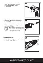
Страница 17: ...3 16 17 5 Screw the spring retainer F onto the cylinder D3 and firmly secure it See Figure 16 6 Connect air supply hose to the male plug See Figure 17 7 Set the working pressure at 90psi 6 3bar for best tool performance NOTE Working pressure refers to the air line pressure set to tool when tool is under working conditions 16 ...

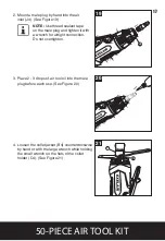
Страница 18: ...e collet jacket B4 counterclockwise by hand or with the large wrench while holding the small wrench on the flats of the collet holder C4 See Figure 21 2 Mount a male plug by hand into the air inlet J4 See Figure 19 NOTE Use thread sealant tape on the male plug and tighten it with a wrench for airtight connection Do not overtighten 17 ...

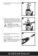
Страница 19: ...o tool when tool is under working conditions 5 Insert a grinding stone P into the collet D4 See Figure 22 6 Tighten the collet jacket B4 clockwise with large wrench while holding the small wrench on the flats of the collet holder C4 Make sure that the grinding stone is installed securely and tightly See Figure 23 WARNING Only use grinding accessories that have a RPM and Torque rating equal to or g...

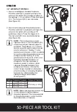
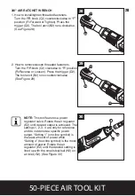
Страница 20: ...l features a power regulator valve 3 Turn the switch D1 slowly forward until desired output is achieved The Settings 1 2 3 do not denote a specific power output but are only for reference Setting 1 is the least amount of power which is suitable for just mounting threaded fasteners on workpiece while Setting 3 is the greatest amount of power which is for tightening threaded fasteners on workpiece T...

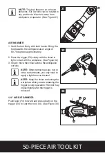
Страница 21: ...verse or Loosen Press the trigger D2 The tool anvil B2 runs counterclockwise See Figure 29 29 30 H2 E2 G2 NOTE This tool features a power regulator valve Rotate the air regulator E2 until desired output is achieved The settings 1 2 3 4 are only for reference and do not denote a specific power output Setting 1 one line symbol is the least amount of power while Setting 4 four line symbol is the most...

Страница 22: ...e trigger C3 slowly with the chisel in light contact with the workpiece See Figure 32 3 Slowly move the chisel across the workpiece surface NOTE When removing scale rust or other contaminants you only need to apply a light force on the tool NOTE Keep the chisel contacting the workpiece while you are releasing the trigger to stop operation The tool may impact briefly after the trigger is released 1...

Страница 23: ... and do not denote a specific power output Setting 1 one line symbol is the lowest speed while Setting 4 four line symbol is the highest speed Rotate the air regulator G4 until the desired setting is lined up with the small steel ball I4 on air inlet J4 See Figure 34 NOTE This tool also features an exhaust deflector H4 which is rotatable to direct air away in any directions See Figure 35 22 ...

Страница 24: ...EM TROUBLESHOOTING CORRECTIVE ACTION POSSIBLE CAUSE CARE AND MAINTENANCE An in line oiler is recommended to be installed on air supply line as it increases tool life and keeps the tool in sustained operation The in line oiler should be regularly checked and filled with air tool oil Proper adjustment of the in line oiler is performed by placing a sheet of paper next to the tool s exhaust ports and ...

Страница 25: ...cover Washer Screw Trigger 1 1 1 1 2 2 2 1 1 1 1 1 1 6 1 1 1 1 4 4 1 22 23 24 25 26 27 28 29 30 31 32 33 34 35 36 37 38 39 40 41 Spring Trigger sleeve Pin Valve sleeve Plunger Washer Set pin Set pin Spring Switch Muffler Screw Oil seal EX1235IW 34 Pin Pin cover Spring O ring Air inlet Soft grip Soft grip 1 1 1 1 1 1 1 1 1 1 1 1 1 1 1 1 1 1 1 1 1 2 AIR IMPACT WRENCH 5 5 4 3 2 1 30 29 20 19 18 17 16...

Страница 26: ...X3860AR1 26 Cylinder Pin 1 1 1 1 1 1 1 1 1 1 1 1 1 1 1 1 1 1 2 1 1 1 1 1 1 4 1 1 29 30 31 32 33 34 35 36 37 38 39 40 41 42 43 44 45 46 47 48 49 50 51 52 53 54 55 Front plate Bearing Washer Thread ring gear Idle gear Gear pin Gear plate Clamp nut Ring gear Bushing Crankshaft Drive bushing Ratchet housing Ratchet yoke F R knob Sleeve Spring Washer Ratchet head Pin Ratchet pawl Thrust washer Retainer...

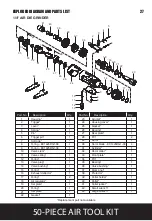
Страница 27: ...d cap EX0445AH1 07 Washer Piston Cylinder Spring retainer Trigger sleeve Spring O ring EX0445AH1 14 1 1 1 1 1 1 1 1 1 1 1 1 1 1 15 16 17 18 19 20 21 22 23 24 25 26 27 28 Trigger Set pin Plug Oil seal EX1235IW 34 Pin Pin cover Spring O ring Air inlet Muffler Screw Soft grip Soft grip Chisel 1 1 1 1 1 1 1 2 1 1 1 1 1 4 4 3 25 24 14 13 15 12 26 23 19 20 22 18 21 9 17 6 7 5 16 27 22 1 2 28 11 10 8 26 ...

Страница 28: ...ator Set plate O ring Set plate Gasket 1 1 1 1 1 1 1 1 1 1 1 1 1 1 1 1 2 1 1 1 1 1 23 24 25 26 27 28 29 30 31 32 33 34 35 36 37 38 39 40 41 42 43 Air inlet Housing cover Gasket Bearing Rear plate Pin Rotor Rotor blade EX1425DG1 30 Cylinder Rotor collar Front plate Pin Bearing Valve bushing Clamp nut Protector Collet holder Collet Collet jacket Small wrench Large wrench 1 1 1 1 1 2 1 4 1 1 1 1 1 1 ...

Страница 29: ...639 Phone 855 G04 MILT 855 464 6458 www exel air com 28 MILTON INDUSTRIES AIR TOOL WARRANTY POLICY 3 YEAR LIMITED WARRANTY Please visit www miltonindustries com to register this product for the 3 Year limited warranty offered by Milton To make any warranty claims or to learn more about the 3 year warranty please visit www miltonindustries com ...

Отзывы: