


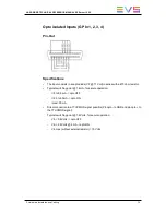


TTL Inputs (GP In 5, 6, 7, 8)
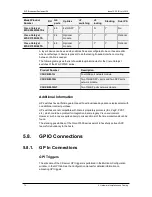
Relay Inputs Pin-Out
The relay must be connected between the ground and the corresponding TTL input on the
DB-25.
TTL Inputs Pin-Out
Each TTL input on the DB-25 is directly connected to the pin of the TTL connector on the
device triggering the GPI. The ground must be common between the DB-25 connector of
the XS server and the external device.
Specifications
•
each pin can be individually configured as an output or an input
•
internal 4K7 pull up to +5 V
•
low level Vi < 1.5 Volt (U12 = 74HC245)
•
high level Vi > 3.5 Volt (U12 = 74HC245)
•
optional TTL compatible level (U12 = 74HCT245)
74
5. Hardware Installation and Cabling
EVS Broadcast Equipment SA
Issue 12.05.B - July 2014
Содержание XS
Страница 1: ...HARDWARE TECHNICAL REFERENCE MANUAL Version 12 05 July 2014 ...
Страница 2: ......
Страница 4: ......
Страница 8: ......
Страница 10: ......
Страница 17: ...Right View Back View HARDWARE TECHNICAL REFERENCE MANUAL XS Server 12 05 3 Hardware Specifications 7 ...
Страница 19: ...Right view Top view HARDWARE TECHNICAL REFERENCE MANUAL XS Server 12 05 3 Hardware Specifications 9 ...
Страница 93: ...Connector Layouts HARDWARE TECHNICAL REFERENCE MANUAL XS Server 12 05 6 Boards Description 83 ...
Страница 94: ...84 6 Boards Description EVS Broadcast Equipment SA Issue 12 05 B July 2014 ...
Страница 96: ...Connectors Layouts 86 6 Boards Description EVS Broadcast Equipment SA Issue 12 05 B July 2014 ...
Страница 98: ...Connectors Layouts 88 6 Boards Description EVS Broadcast Equipment SA Issue 12 05 B July 2014 ...
Страница 100: ...Connectors Layouts 90 6 Boards Description EVS Broadcast Equipment SA Issue 12 05 B July 2014 ...
Страница 113: ...Illustration HARDWARE TECHNICAL REFERENCE MANUAL XS Server 12 05 6 Boards Description 103 ...
Страница 116: ......
Страница 117: ......