background image


Instructions 


- 16 - 

ERC-1005 


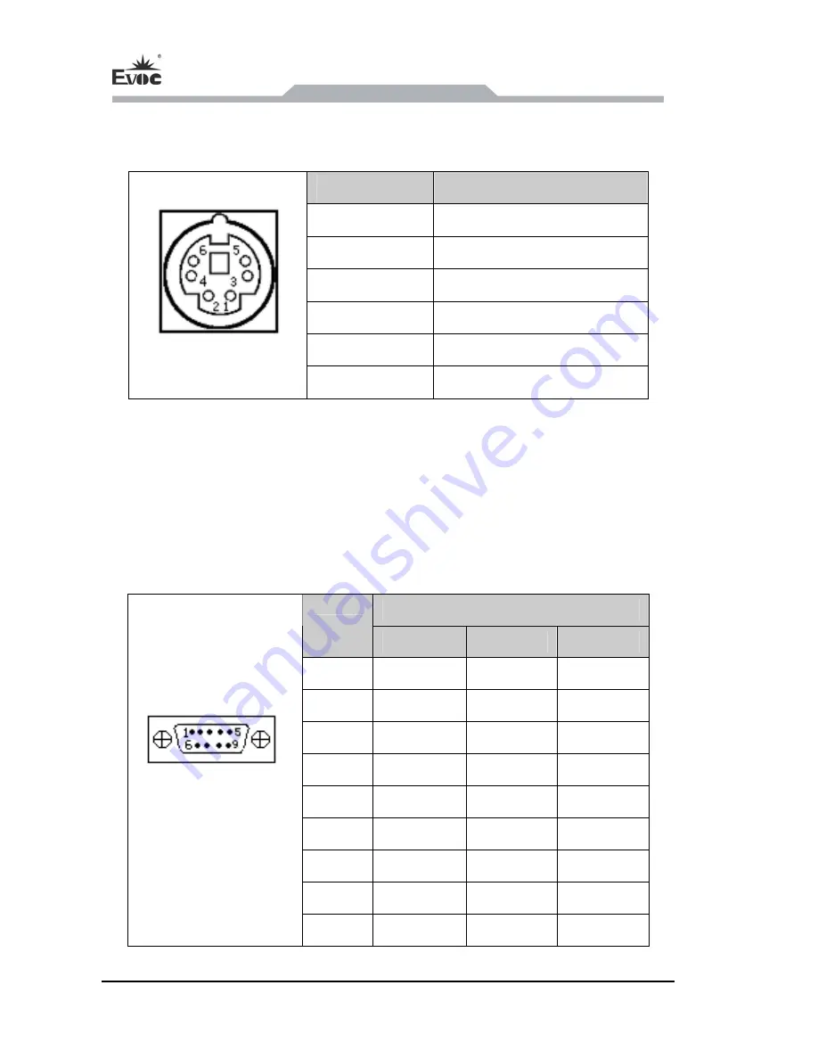
4.4.8 Mouse & Keyboard Connector (adopts standard 2-in-1 mouse 

& keyboard connector) 

Pin 

Signal Name 

1 KB_DATA 

2 MS_DATA 

3 GND 

4 +5V 

5 KB_CLK 


KM1 

6 MS_CLK 


4.4.9 Serial Port 

COM1 and COM2 support RS-232/RS-422/RS-485 mode selection; COM1 supports 

Modem wake-up function. COM3 ~ COM5 are isolation serial ports: COM3 and 

COM5 only support RS-232 mode, COM4 can switch among RS-232/RS-422/RS485 

mode. COM6 ~ COM10 support RS-232 mode. The pin definitions are as follows: 

Signal Name 

Pin 

RS-232 

RS-422 

RS-485 

1 DCD# TXD- Data- 

2 RXD TXD+ 

Data+ 

3 TXD RXD+ NC 

4 DTR# RXD-  NC 

5 GND GND GND 

6 DSR#  NC  NC 

7 RTS#  NC  NC 

8 CTS#  NC  NC 

COM1/COM2 

COM6 ~ COM10 

9 RI#  NC  NC 


Содержание ERC-1005

Страница 1: ...特种计算机 Industrial Computer 产品说明书 User Manual ERC 1005 轨道交通 AFC 系统终端 AFC Terminal for Metro Version C01 ...

Страница 2: ...e manual can only be handled by qualified and professional personnel During operation please follow the respective instructive manuals especially the safety warnings The professional personnel have been trained and possess relevant experiences therefore he she could be aware of the risks of the product system and avoid possible damages EVOC Product Please pay attention to the following instruction...

Страница 3: ...ieval system or transmitted in any form or by any means mechanical electronic photocopied recorded or otherwise without the prior written permission from the manufacturer Trademarks EVOC is a registered trademark of EVOC Intelligent Technology Co Ltd Other product names mentioned herein are used for identification purposes only and may be trademark and or registered trademarks of their respective ...

Страница 4: ...e Product within the manual stands for EVOC ERC 1005 Instructions Safety instructions To avoid property losses or individual injury please pay attention to the safety instructions within the manual The warnings within the manual are marked with warning triangle which is dependent upon the scale of the potential hazard ...

Страница 5: ...e to Power 7 4 Instructions 8 4 1 Product Outline 8 4 1 1 PC with Movable Scaffolding 8 4 1 2 PC with Fixation Apparatus 8 4 2 Product Appearance and Installation Dimensions 9 4 2 1 PC with Movable Scaffolding 9 4 2 2 PC with Fixation Apparatus 10 4 3 External Structure 11 4 4 Pin Definitions 12 4 4 1 Power Connector 12 4 4 2 Audio Connector 12 4 4 3 USB Port USB1 USB6 are standard USB ports 12 4 ...

Страница 6: ...6 Status Indicator 19 5 Assembly and Maintenance 20 5 1 Overall Assembly Drawing 20 5 2 Installing the Cover 21 5 3 Removal and Installation of Motherboard 21 5 3 1 Installing the Motherboard 21 5 3 2 Removing the Motherboard 22 5 4 Removing the Driver 22 5 5 Installing the Wall mounted Bar 23 6 Installing the Drivers 24 7 Appendix 25 7 1 Troubleshooting and Solutions 25 ...

Страница 7: ...excellent dust proof heat dissipation and anti vibration performances ERC 1005 is the main control unit of the AFC system for metro which is used as the main control unit of the AGM TVM and BOM in AFC system The PC complies with GB 9254 2008 and GB T 17626 2008 standards 1 2 Product Specifications Items Definitions Microprocesso r Intel Atom Processor N455 D525 CPU on board Chipset Intel ICH8M Mem...

Страница 8: ...t DVI I connector bring out Six USB2 0 ports two on the front panel while the other four on the rear panel One PS 2 keyboard mouse connector One AUDIO connection vertical socket one MIC IN and one LINE OUT Two 16 chanenl GPIO connectors GPIO1 is digital GPIO while GPIO2 is isolation GPIO One CF card slot optional with CF card One LPT connector Dimensions excluding the hangers 245mm W x 117 8mm H x...

Страница 9: ...ility level 2 GB T 17626 8 2006 Power frequency magnetic field level 2 GB T 17626 11 2008 Voltage dips and short supply interruption Reliability MTBF 50000h MTTR 20 min Safety Meets the basic requirements of GB4943 2001 Mechanical and Environment Adaptability Anti vibration 5 17Hz 1 0mm amplitude 17 200Hz 1 0g acceleration Anti shock 10g acceleration 11ms duration Power Feature Input Voltage Curre...

Страница 10: ...ckage box when it is not used And warehouse temperature should be 0 C 40 C and relative humidity should be 20 85 In the warehouse there should be no harmful gas inflammable explosive products and corrosive chemical products and strong mechanical vibration shock and strong magnetic field interference The package box should be at least 10cm above ground and 50cm away from wall thermal source window ...

Страница 11: ...mentation is required for initial device debugging which is a component of the device When doing the initial examination please check whether there are distinct damages to the device caused during the transport Please check whether the delivery contains the intact device and all of the independently ordered accessories Please contact the customer service when any unconformity or transportation dam...

Страница 12: ...ustrial application can be used When operating the PC hot swappable IO modules USB can be used The IO devices without hot swap function can only be connected when the PC is powered off 3 2 Product Grounding Low impedance ground connection is more helpful to release the interference produced by the external cables the signal cables or the cables connecting the IO module to the grounding system Grou...

Страница 13: ...ease refer to the pin definitions of the power connector for detailed information Connect the power cord with the connector and press down the switch with the silkscreen of The green power LED indicator on the rear panel of the PC is lit and the PC is powered on Danger Please disconnect the power and data cables during thunder storm Note To completely isolate the device from the power supply pleas...

Страница 14: ...Instructions 8 ERC 1005 4 Instructions 4 1 Product Outline 4 1 1 PC with Movable Scaffolding 4 1 2 PC with Fixation Apparatus ...

Страница 15: ...Instructions ERC 1005 9 4 2 Product Appearance and Installation Dimensions 4 2 1 PC with Movable Scaffolding Unit mm ...

Страница 16: ...Instructions 10 ERC 1005 4 2 2 PC with Fixation Apparatus Unit mm ...

Страница 17: ...Handle Movable bracket LINE OUT MIC LAN2 USB3 USB4 LAN1 USB1 USB2 COM2 LPT COM1 CF card cover VGA1 LVDS MS KB Clearing CMOS switch RESET switch PWR indicator Assisting Handle HDD indicator VGA2 Assisting Handle COM3 COM4 21 COM5 COM6 22 COM7 COM8 23 COM9 24 GPIO1 25 COM10 26 GPIO2 27 Assisting Handle ...

Страница 18: ...Power switch Power input terminal 4 4 Pin Definitions 4 4 1 Power Connector Pin Signal Name 1 2 3 NC 4 NC 4 4 2 Audio Connector Pin Signal Name 1 LINE_OUT AUDIO 2 MIC_IN 4 4 3 USB Port USB1 USB6 are standard USB ports Pin Signal Name 1 5V 2 USB_Data 3 USB_Data USB1 2 USB3 4 USB5 6 4 GND ...

Страница 19: ...ator Green 1000Mbps Blink Data being transmitted Orange 100Mbps Off No data being transmitted Off 10Mbps 4 4 5 Parallel Port Adopts standard LPT connector Pin Signal Name Pin Signal Name 1 STB 14 AFD 2 PD0 15 ERR 3 PD1 16 INIT 4 PD2 17 SLIN 5 PD3 18 GND 6 PD4 19 GND 7 PD5 20 GND 8 PD6 21 GND 9 PD7 22 GND 10 ACK 23 GND 11 BUSY 24 GND 12 PE 25 GND LPT 13 SLCT ...

Страница 20: ...annel 18bit LVDS connector adopting standard DB24 4 connector Note this connector supports LVDS signals please do not connect the DVI cable with the DVI connector on the display directly Pin Signal Name Pin Signal Name 1 LVDS_D2 2 LVDS_D2 3 GND 4 BKLTEN 5 BKLTCTL 6 NC 7 NC 8 5V 9 LVDS_D1 10 LVDS_D1 11 GND 12 VDD_LCD 13 VDD_LCD 14 5V 15 GND 16 12V 17 LVDS_D0 18 LVDS_D0 19 GND 20 GND 21 GND 22 GND 2...

Страница 21: ...me 1 DI16 2 DI17 3 DI18 4 DI19 5 DI20 6 DI21 7 DI22 8 DI23 9 DI24 10 DI25 11 DI26 12 DI27 13 DI28 14 DI29 15 DI30 16 DI31 17 GND 18 GND GPIO1 19 5V 20 12V Pin Signal Name Pin Signal Name 1 IDO0 2 IDO1 3 IDO2 4 IDO3 5 IDO4 6 IDO5 7 IDO6 8 IDO7 9 EO GND 10 EO COM 11 IDO10 12 IDO11 13 IDO12 14 IDO13 15 IDO14 16 IDO15 17 IDO16 18 IDO17 GPIO2 19 EI COM1 20 EI COM2 ...

Страница 22: ...22 RS 485 mode selection COM1 supports Modem wake up function COM3 COM5 are isolation serial ports COM3 and COM5 only support RS 232 mode COM4 can switch among RS 232 RS 422 RS485 mode COM6 COM10 support RS 232 mode The pin definitions are as follows Signal Name Pin RS 232 RS 422 RS 485 1 DCD TXD Data 2 RXD TXD Data 3 TXD RXD NC 4 DTR RXD NC 5 GND GND GND 6 DSR NC NC 7 RTS NC NC 8 CTS NC NC COM1 C...

Страница 23: ... 422 RS 485 mode selection for COM2 motherboard Mode Selection Pin Setting RS 232 Default RS 422 RS 485 JP8 1 2 5 6 3 4 JP9 1 3 2 4 3 5 4 6 3 5 4 6 JP8 JP9 JP10 JP10 1 3 2 4 3 5 4 6 3 5 4 6 Signal Name Pin RS 232 RS 422 RS 485 1 NC TX Data 2 RXD TX Data 3 TXD RX NC 4 NC RX NC 5 GND GND GND 6 NC NC NC 7 NC NC NC 8 NC NC NC COM3 COM4 COM5 9 NC NC NC Note the data transmission direction is controlled...

Страница 24: ...ction for COM4 IO board Mode Selection Pin Setting RS 232 Default RS 422 RS 485 1 ON OFF 2 OFF ON 3 ON ON SW1 4 NC NC 1 OFF ON 2 OFF ON 3 NC NC SW2 4 NC NC 1 ON OFF OFF 2 OFF ON ON 3 NC NC NC SW3 4 NC NC NC 1 ON ON 2 ON OFF 3 ON ON SW4 4 ON OFF 1 ON OFF OFF 2 OFF ON ON 3 ON OFF OFF SW1 SW5 SW5 4 OFF ON ON ...

Страница 25: ...ing CMOS button when the PC is powered off and disconnected from power supply Pressing button signal will reset BIOS and restore the BIOS setting to factory default value Reset button Use a sharp point object or clip to operate the reset button Pressing button signal will reset the hardware The PC will be rebooted cold reset 4 6 Status Indicator Display Meaning LED Description Off Disconnected fro...

Страница 26: ...Assembly and Maintenance 20 ERC 1005 5 Assembly and Maintenance 5 1 Overall Assembly Drawing Item Description Item Description 1 Upper cover 2 Chassis 3 Bottom cover 4 Expansion board 5 Motherboard ...

Страница 27: ...al and Installation of Motherboard 5 3 1 Installing the Motherboard 1 Push the motherboard gently along the guide rail into the corresponding slot 2 When approaching the backplane connector open the assisting handles outward with both hands then buckle the chassis inward with force and push the board inward at the same time 3 When the board is properly in position tighten the two captive screws on...

Страница 28: ...motherboard 3 Remove the expansion card in the same way 5 4 Removing the Driver 1 The hard disk module has been installed on the motherboard before removing the hard disk module please draw the motherboard out of the chassis 2 Remove the four screws fixing the hard disk bracket as shown in the figure 3 Gently remove the hard disk module away from the SATA connector on motherboard to take the modul...

Страница 29: ...ovable bracket and the guide rail for the left movable bracket fix the supporting arm of the movable bracket and the guide rail for the left movable bracket with corresponding truss head screws apply a gasket as shown in the above figure 5 Install the mounting bracket on the right side of the chassis the right bracket the guide rail for the right movable bracket and the supporting arm of the right...

Страница 30: ...Installing the Drivers 24 ERC 1005 6 Installing the Drivers Regarding the driver program of this product please refer to the enclosed CD ...

Страница 31: ...oard The luminance control is set to Black Increase the screen luminance by luminance control Please refer to the instructions of the display for detailed information The external display is black Power cable or display cable is not connected 1 Please check whether the power cable is correctly connected with the display the system unit or the ground port 2 Please check whether the display cable is...

Страница 32: ...y the booting priority of the device in the Boot menu of BIOS setting or include that device into the booting priority The HDD power cable or data cable is not connected well Check whether the power cable and the data cable of the hard disk the hard disk shall be installed with operating system and is bootable are well connected No system disk can be found when powering on System files on the hard...

Отзывы: