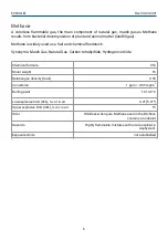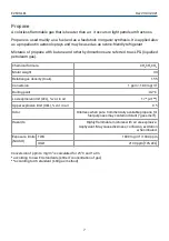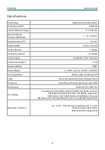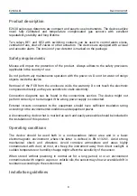
E2630-LEL
Rev 23.03.2021
Connections
1. Unscrew four lid screws and detach the lid from the device;
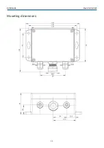
2. Attach the device to the wall using provided screws through the side mounting holes or
key slots (This step may be done before step 1, consider your convenience).
3. Use two M16 cable glands to let in the cables of the power supply and of the external
devices.
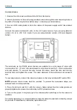
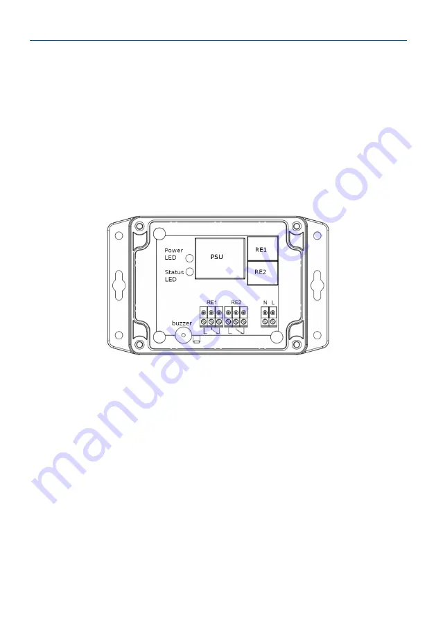
Connect the power terminals N and L to the 24 V power source if you are using detector
version -24 or to 230 V AC mains if you are using detector version -230 (see diagram
below).
The terminals on the E2630 series devices are suitable for a wide range of wires with
cross-section 0,2...1,5 mm
2
. We recommend to strip the wire end by 5...6 mm and use the
wire end sleeves. To connect the wire, loosen the screw, insert the wire end into the
terminal hole and tighten the screw. The outer diameter of the cable must not exceed 8
mm.
To use relay outputs, connect the chosen actuators to the relay terminals RE1 and/or RE2.
NOTE! Actuator short-circuits shall be avoided. To protect the instrument relays, use
external fuses or safety switches.
3. Place the lid back and fix it with the screws. Make certain that the cable glands are
properly tightened to ensure the conformity to IP65 protection class.
4. Turn on the power. It may take up to five minutes after switching on for the sensor to
stabilize.
For stable operating, it is recommended to keep the detector powered constantly, except
for periods of maintenance, calibration, replacement, etc.
12


