TSMIP-10GE Series
IP Transport Stream Monitor
Page-8
Revision 1.0
g. Type x to exit Network Configuration menu.
h. Type x to exit and save configuration.
i. The same steps can be done for Data 1 (Data Main) and Data 2 (Data Redundant) interfaces
j. All other Data ports must be configured through VLPro
3.2.
SET UP INPUTS AND OUTPUTS
1. Connect the Ethernet cable to the CONTROL Ethernet ports on the rear panel and the other end to
an Ethernet switch. See Figure 3-2.
2. Connect Ethernet cables to desired ports and the other end to the Ethernet switch. User can
connect to 10GE ports.
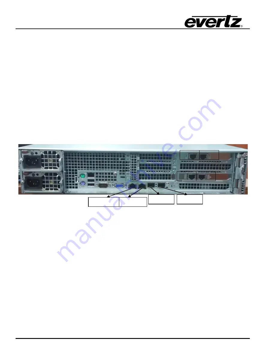
Figure 3-2 : TSMIP-10GE Rear Panel
Control 1&2:
These connectors allow the TSMIP to be able to communicate with the computer,
allowing for the user to control the TSM through the interface of choice.
Note:
Control 2 is not used.
Data1:
Data Port 1
Data2:
Data Port 2
Data3:
Data Port 3
Data4:
Data Port 4
10GE-1 and 10GE-2:
To access the 10GE Data port, connect a full duplex fiber cable to the
10GE1 and 10GE2 SFP ports on the rear panel. See specifications on the
SFP modules that need to be inserted before fiber connections can be
made.
Control2
10GE-2
10GE-1
Data1
Data2
Data3
Data4
Control1
Содержание TSMIP-10GE
Страница 2: ...This page left intentionally blank ...
Страница 8: ...TSMIP 10GE Series IP Transport Stream Monitor Page iv Revision 1 0 This page left intentionally blank ...
Страница 10: ...TSMIP 10GE Series IP Transport Stream Monitor Page 2 Revision 1 0 Figure 1 1 TSMIP 10GE Front and Rear Panel ...
Страница 12: ...TSMIP 10GE Series IP Transport Stream Monitor Page 4 Revision 1 0 This page left intentionally blank ...
Страница 14: ...TSMIP 10GE Series IP Transport Stream Monitor Page 6 Revision 1 0 This page left intentionally blank ...
Страница 18: ...TSMIP 10GE Series IP Transport Stream Monitor Page 10 Revision 1 0 This page left intentionally blank ...
Страница 50: ...TSMIP 10GE Series IP Transport Stream Monitor Page 42 Revision 1 0 This page left intentionally blank ...


