PROGUARD Quick Start Guide
Revision 1.0
Page -
25
3.3.1. SDI I/O
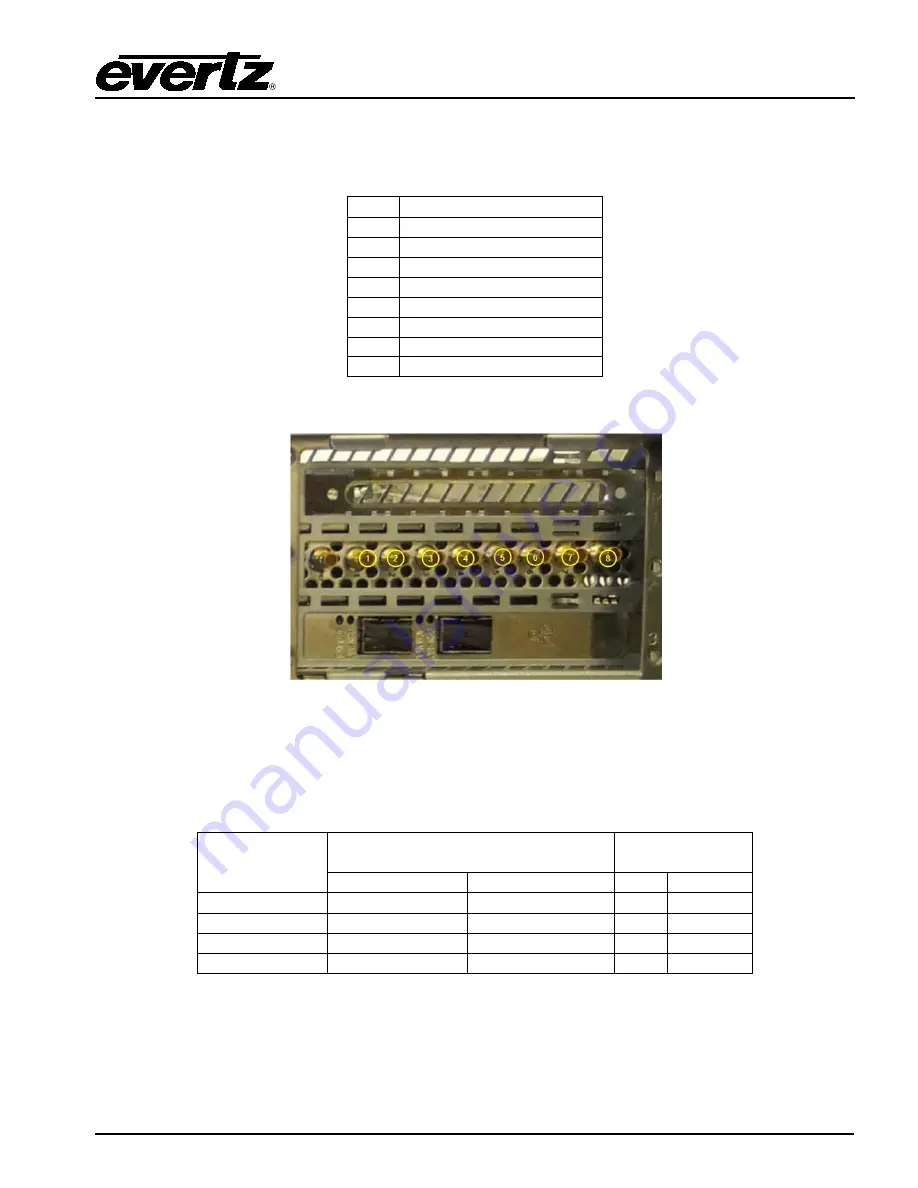
The SDI inputs are set up according to Table 3-3 below. The corresponding SDI inputs on the rear
panel of the ProGuard device are shown in Figure 3-36.
BNC Dual Seat (3G/HD/SD)
1
Program Output (Seat 1)
2
Main Input (Seat 1)
3
Not used
4
Aux Input (Seat 1)
5
Program Output (Seat 2)
6
Main Input (Seat 2)
7
Not used
8
Aux Input (Seat 2)
Table 3-3: SDI I/O mapping
Figure 3-36: SDI I/O Rear Panel View
3.3.2. Compressed IPTS I/O
The uncompressed 10G IP I/O are set up according to Table 3-4 below. The corresponding 10G I/O
ports on the rear panel of the ProGuard device are shown in Figure 3-37.
Port
(Main/Backup)
Dual Seat (3G/HD/SD)
Single Seat
(UHD)
Input
Output
Input Output
1/2
Main (Seat 1)
Program (Seat 1) Main Program
1/2
Aux (Seat 1)
3/4
Main (Seat 2)
Program (Seat 2) Aux
3/4
Aux (Seat 2)
Table 3-4: 10G IP I/O Mapping.


