background image


PROGUARD Quick Start Guide 


Page - 26 

Revision 1.0


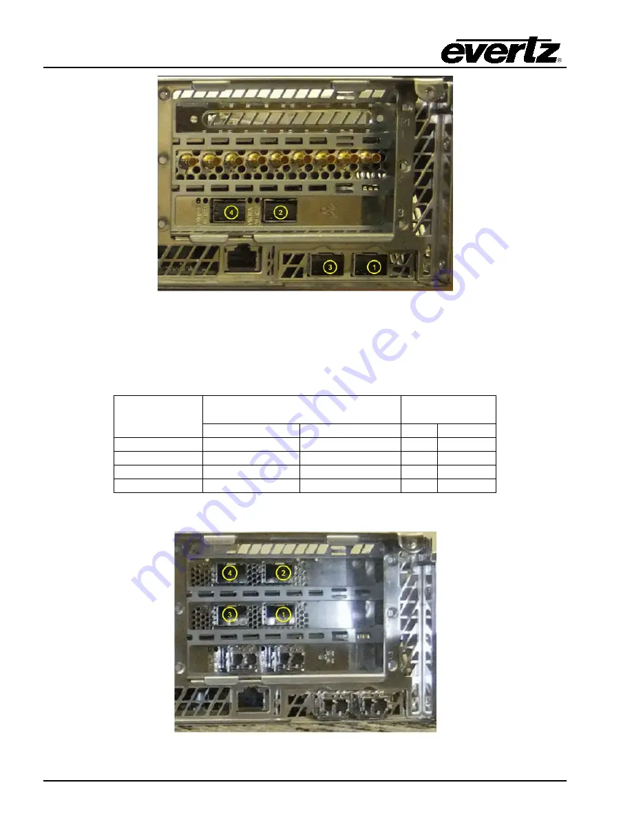
Figure 3-37: 10G IP I/O Rear Panel View 


3.3.3.  Uncompressed 25G IP I/O 

The uncompressed 25G IP I/O are set up according to Table 3-5 below. The corresponding 25G I/O 

ports on the rear panel of the ProGuard device are shown in Figure 3-38. 


Port 

(Main/Backup) 

Dual Seat (3G/HD/SD) 

Single Seat 

(UHD) 

Input 

Output 

Input  Output 

1/2 

Main (Seat 1) 

Program (Seat 1)  Main  Program 

1/2 

Aux (Seat 1) 


3/4 

Main (Seat 2) 

Program (Seat 2)  Aux 


3/4 

Aux (Seat 2) 


Table 3-5: 25G I/O Mapping 


Figure 3-38: 25G IP I/O Rear Panel View 

Содержание PROGUARD

Страница 1: ... evertz com Version 1 0 November 2021 The material contained in this manual consists of information that is the property of Evertz Microsystems and is intended solely for the use of purchasers of the PROGUARD Evertz Microsystems expressly prohibits the use of this manual for any purpose other than the operation of the device All rights reserved No part of this publication may be reproduced without...

Страница 2: ...This page left intentionally blank ...

Страница 3: ...ird grounding prong The wide blade or the third prong is provided for your safety If the provided plug does not fit into your outlet consult an electrician for replacement of the obsolete outlet Protect the power cord from being walked on or pinched particularly at plugs convenience receptacles and the point where they exit from the apparatus Only use attachments accessories specified by the manuf...

Страница 4: ...IGITAL DEVICE OR PERIPHERAL This equipment has been tested and found to comply with the limits for a Class A digital device pursuant to Part 15 of the FCC Rules These limits are designed to provide reasonable protection against harmful interference when the equipment is operated in a commercial environment This equipment generates uses and can radiate radio frequency energy and if not installed an...

Страница 5: ...ty offered by Evertz in relation to this product is the Evertz standard limited warranty stated in the sales contract or order confirmation form Although every attempt has been made to accurately describe the features installation and operation of this product in this manual no warranty is granted nor liability assumed in relation to any errors or omissions unless specifically undertaken in the Ev...

Страница 6: ...PROGUARD Quick Start Guide Page ii Revision 1 0 This page left intentionally blank ...

Страница 7: ... 3 1 4 Network Configuration 11 3 1 4 1 Control Network 11 3 1 4 1 1 Control Port Configuration 11 3 1 4 1 2 Show route table 12 3 1 4 2 Data Network 13 3 1 4 2 1 Data Port Configuration 13 3 1 5 System Configuration 14 3 1 5 1 Host Name 14 3 1 5 2 Date 14 3 1 5 3 Time 14 3 1 5 4 Time Zone 14 3 1 5 5 Password 14 3 1 6 Restart Application 14 3 1 7 System Control 14 3 1 8 Software Version 15 3 1 9 E...

Страница 8: ...r Panel View 5 Figure 3 17 Configuration Main Menu 7 Figure 3 18 I O Type Configuration Menu 7 Figure 3 19 I O Type Options 8 Figure 3 20 Standard Options 8 Figure 3 21 PTP Configuration Menu 9 Figure 3 22 PTP Status Window 9 Figure 3 23 PTP Domain Configuration 9 Figure 3 24 PTP Port Configuration 10 Figure 3 25 IPMI Configuration Menu 10 Figure 3 26 Network Configuration Menu 11 Figure 3 27 Cont...

Страница 9: ...nt Profiles 21 Figure 3 13 Applying Sound Concealment Profile to Output Feed 22 Figure 3 14 Recording Options 23 Figure 3 15 Recording in Progress 23 Figure 3 16 User Control Settings 24 Figure 3 36 SDI I O Rear Panel View 25 Figure 3 37 10G IP I O Rear Panel View 26 Figure 3 38 25G IP I O Rear Panel View 26 Tables Table 2 1 Front View Labels Functions 3 Table 2 2 Control Panel Buttons and LEDs 4 ...

Страница 10: ...PROGUARD Quick Start Guide Page vi Revision 1 0 This page left intentionally blank ...

Страница 11: ...defocus video content Insert video black static animated graphic or safe content clip Audio Protection Options Switch to alternative safe feed Mute shuffle or swap audio channels Insert safe audio content or beep Configurable Operator Reaction Time ProGuard provides an easy to configure reaction time from 1 5 seconds allowing your operators to react reliably to eliminate offensive behavior or acti...

Страница 12: ...y system with standard SDI I O PROGUARD 10G 2 Dual channel 3G HD SD broadcast delay system with 10G I O 4x 10GbE ports Native support for SMPTE ST 2110 and ST 2022 6 PROGUARD 3G VM Single channel 3G HD SD broadcast delay system for cloud application Compressed MPEG 2 H 264 I O Contact factory for details PROGUARD UHD VM Single channel 3G HD SD broadcast delay system for cloud application Compresse...

Страница 13: ...o support 2022 6 and 2110 output formats 2 1 1 Front View Physically the PROGUARD occupies 2 rack unit of space The front of the PROGUARD is shown in Figure 2 1 below The front accessible drive bays as well as the status activity LEDs a soft reset button and system power button are readily visible Figure 2 1 Front View of PROGUARD Front Panel Installed LABEL FUNCTION HDD 1 through 8 Local Storage ...

Страница 14: ...H2 C Power Failure The LED flashes if there is a power supply failure H Information LED This LED flashes at different rates and different colors to indicate one of several failures that may have occurred in the unit The list below describes the different LED states and failures Fast Blinking Red 1x sec Fan Fail Solid Red CPU Overheat Slow Blinking Red 1x 4 sec Power Fail Solid Blue Local UID Butto...

Страница 15: ... Supply 1 2 Power Supply 2 3 OS SSDs 4 eth0 5 eth1 6 eth4 7 eth5 8 VGA 9 USB 10 IPMI 11 GPU 12 eth3 10G 13 eth2 10G 14 eth7 10G 15 eth6 10G 16 SDI Card 0 most left is reference then 1 8 in increasing order from left to right Table 2 3 Port Labels Functions Figure 2 4 ProGuard with 25G I O Option Rear Panel View ...

Страница 16: ...U state PSU LED Color PSU State Green Indicates power is being supplied to the PSU the PSU is in good working condition and the unit is on Amber Indicates power is being supplied to the PSU and the unit is off Table 2 5 PSU State Each PSU provides audible tone for notification in the event of a PSU fails or looses power 2 2 POWERING UP THE UNIT To power up the PROGUARD unit depress the power butto...

Страница 17: ...r admin with password admin The configuration menu can be accessed over SSH after initial setup with the credentials admin admin Navigate the menu using the arrow keys or by clicking the desired menu options The UP and DOWN arrow keys can be used to navigate between menu items The LEFT and RIGHT arrow keys are used to select between confirmation choices e g OK or Back Menu items are selected by pr...

Страница 18: ...r to select between SDI and ST2110 I O The selected I O type applies to both ProGuard paths Figure 3 3 I O Type Options 3 1 1 2 Standard This control allows the user to select the video standard used for playout The selected standard applies to both ProGuard paths Figure 3 4 Standard Options ...

Страница 19: ...d view the status of the PTP lock Figure 3 5 PTP Configuration Menu 3 1 2 1 View Status This menu option displays the lock status of PTP The status will display Locked if PTP is currently locked or Unlocked if PTP lock has not been established Figure 3 6 PTP Status Window 3 1 2 2 Domain This control allows the user to set the PTP domain number Figure 3 7 PTP Domain Configuration ...

Страница 20: ...disruptions 3 1 3 IPMI Configuration The IPMI menu allows the user to configure the network settings for IPMI control Figure 3 9 IPMI Configuration Menu The IPMI type option allows the user to select between using DHCP or a Static network configuration for the IPMI interface If a static network configuration is selected the IP address netmask and gateway can be configured by selecting the associat...

Страница 21: ...for the control ports This menu provides the option to configure the IP address netmask and gateway for each control interface as well as view the current route table Figure 3 11 Control Network Configuration Menu 3 1 4 1 1 Control Port Configuration The IP address netmask and gateway are displayed for each control interface Refer to section 2 1 2 Rear View for the mapping between the interface na...

Страница 22: ...ddress Save and apply the changes to the network settings by selecting the Save and Apply menu option Figure 3 13 IP Address Configuration NOTE Applying changes to the network settings restarts the network interfaces and may cause a temporary service interruption 3 1 4 1 2 Show route table This control displays the current route table Figure 3 14 Route Table ...

Страница 23: ... section 3 3 I O LAYOUT for the mapping between the ENETs and the physical ports on the rear panel of the device Configure the IP address and netmask for each port by selecting the associated menu option and entering the desired address Apply the changes to the network settings by selecting the Apply configuration menu option Changes to the data port settings may require a reboot of the device aft...

Страница 24: ...ntrol allows the user to set the date for the system 3 1 5 3 Time This control allows the user to set the time for the system 3 1 5 4 Time Zone This control allows the user to set the time zone for the system 3 1 5 5 Password This control allows the user to change the password for the admin user 3 1 6 Restart Application The Restart Application menu option allows the user to restart the ProGuard a...

Страница 25: ... the user to logout of the configuration shell The escape key can also be used to exit the shell 3 2 CONTROL USER INTERFACE PROGUARD offers a Control UI accessed through a web browser for easy control of the device To launch the PROGUARD control UI open a web browser such Firefox Enter the IP address followed by canvas e g 172 18 125 11 canvas and press Enter The control UI will open to a Seat Sel...

Страница 26: ...lect a seat by clicking on one of the seat options After clicking a seat an Enter password prompt will appear as shown in Figure 3 2 Enter the password for the seat and hit Enter The user will then be directed to the UI for that seat as shown in Figure 3 3 Figure 3 21 Enter password Prompt Figure 3 22 Control UI ...

Страница 27: ...s shown in Figure 3 5 The Main feed is the unaltered program source before any concealment profiles have been applied The Aux feed is the auxiliary or safe feed that the Program feed can be switched to for concealment The Program feed is the altered video feed after concealment profiles have been applied Figure 3 24 Preview of the Main Auxiliary and Program Video Feeds and their Audio Levels The u...

Страница 28: ...provides two buttons that can be used for applying concealment profiles to the output video and audio as shown in Figure 3 8 Clicking the PICTURE button applies the selected video concealment profile to the Program feed for the duration that the button is held Clicking the SOUND button applies the selected audio concealment profile to the Program feed s audio for the duration that the button is he...

Страница 29: ...eloaded with seven video concealment profiles which are listed in Table 3 1 In addition the user can define and upload their own custom concealment profiles Refer to section 5 4 for list of supported file formats Label Description AUX INPUT Toggle Program input from Main to Aux default is Main when not applied BLUR_EFFECT_20 Apply blur effect at 20 level to Program output BLUR_EFFECT_40 Apply blur...

Страница 30: ...g the PICTURE tab again To apply the selected profile to the Program feed click the PICTURE button below the Program preview as shown in Figure 3 11 Figure 3 30 Applying a Video Concealment Profile to the Output Feed NOTE The picture concealment profile is only applied for the duration that the PICTURE button is held Once the button has been released the profile is no longer applied ...

Страница 31: ...the Program feed AUX_7_8 Shuffles channel 7 and 8 from the Aux feed to channel 1 and 2 of the Program feed AUX_1_2 Shuffles channel 1 and 2 from the Aux feed to channel 1 and 2 of the Program feed Table 3 2 Default Audio Concealment Profiles To apply a profile to the audio output click the SOUND tab on the configuration panel The audio profiles will be displayed in a drop down menu as shown in Fig...

Страница 32: ... played out to the Program feed using the LOOP_RECORDING profile under the PICTURE tab as described in 3 2 4 1 Picture The duration of the recording can be set using the RECORD DURATION option The RECORD DURATION option specifies the length of the recording in seconds and the maximum duration can be set to 600 seconds 10 minutes The feed to record from can be selected using the PORT SELECTION opti...

Страница 33: ...ecording can then be started by clicking the RECORD button as shown in Figure 3 15 The RECORD button remains highlighted until the recording is complete Figure 3 34 Recording in Progress NOTE Once the RECORD button has been pressed the record operation cannot be cancelled or changed The user must wait until the current recording has finished before starting a new one ...

Страница 34: ...e applied by clicking the APPLY button below the delay options How quickly the concealment profile is applied to the output can be set using the USER REACTION TIME option The USER REACTION TIME option specifies how many frames in the past the selected concealment profile should be applied to the Program feed after the user presses the PICTURE or SOUND buttons The USER REACTION TIME option can be e...

Страница 35: ... Seat 2 6 Main Input Seat 2 7 Not used 8 Aux Input Seat 2 Table 3 3 SDI I O mapping Figure 3 36 SDI I O Rear Panel View 3 3 2 Compressed IPTS I O The uncompressed 10G IP I O are set up according to Table 3 4 below The corresponding 10G I O ports on the rear panel of the ProGuard device are shown in Figure 3 37 Port Main Backup Dual Seat 3G HD SD Single Seat UHD Input Output Input Output 1 2 Main S...

Страница 36: ...to Table 3 5 below The corresponding 25G I O ports on the rear panel of the ProGuard device are shown in Figure 3 38 Port Main Backup Dual Seat 3G HD SD Single Seat UHD Input Output Input Output 1 2 Main Seat 1 Program Seat 1 Main Program 1 2 Aux Seat 1 3 4 Main Seat 2 Program Seat 2 Aux 3 4 Aux Seat 2 Table 3 5 25G I O Mapping Figure 3 38 25G IP I O Rear Panel View ...

Страница 37: ... 424M 3G SMPTE 292M HD and SMPTE 259M SD IP I O SMPTE 2110 SMPTE 2022 6 Video Standard 525i 625i 720p 50 720p 59 94 1080i 50 1080i 59 94 1080p 50 1080p 59 94 Video Sample Format 4 2 2 Y C 8 bit 10 bit 4 3 AUDIO SUPPORT Support for PCM HD SD SDI embedded per SMPTE 272M Support for 16 bit 20 bit and 24 bit samples 4 4 GRAPHICS SUPPORT Supported Overlay File Formats TGA TIFF PNG JPG and MOV 4 5 TIME ...

Страница 38: ...OGUARD Power Supply 100 240V AC 11 4 4 A 50 60Hz auto sensing Rating 1100 W 9 565 A Operating Environment Operating Temperature 10 to 35 C 50 to 95 F Non operating Temperature 40 to 70 C 40 to 158 F Operating Relative Humidity 20 to 95 non condensing Non operating Relative Humidity 5 to 95 non condensing RoHS Compliant 4 10 DIMENSIONS PROGUARD 17 25 Wx 3 5 Hx 28 D 439 mm x 89mm x 712mm Gross Weigh...

Отзывы: