background image

CP-2232E 

Remote Control Panel


Revision 1.1 

Page 19


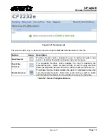
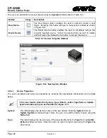
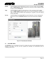
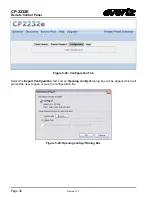
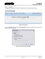
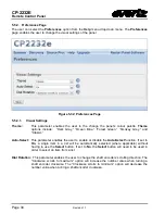
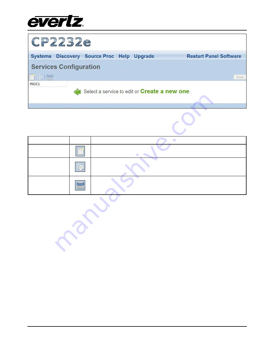
Figure 5-11: Services List 

 
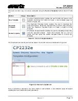
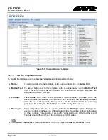
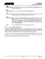
The user can add, copy, or remove a service using the 

Service 

buttons listed in Table 5-2: 


Button 

Image 

Description 

New Service 


The 

New  Service

  button enables the user to add and create a new 

service. Selecting this button will open a new service page. 

Duplicate 
Services 


The 

Duplicate  Services 

button enables the user to duplicate the 

selected  service.  Select the service  that you wish to copy and then 
press the 

Duplicate Services

 button to create a replica of that service. 

Delete Services 


The 

Delete Services

 button enables the user to completely remove the 

currently selected service.  Select the service  that you wish to delete 
and then press the 

Delete Services

 button to remove the template. 

Table 5-2: Service Template Buttons 


Содержание CP-2232E

Страница 1: ...com Version 1 1 July 2013 The material contained in this manual consists of information that is the property of Evertz Microsystems and is intended solely for the use of purchasers of the CP 2232E Evertz Microsystems expressly prohibits the use of this manual for any purpose other than the operation of the device All rights reserved No part of this publication may be reproduced without the express...

Страница 2: ......

Страница 3: ...ird grounding prong The wide blade or the third prong is provided for your safety If the provided plug does not fit into your outlet consult an electrician for replacement of the obsolete outlet Protect the power cord from being walked on or pinched particularly at plugs convenience receptacles and the point where they exit from the apparatus Only use attachments accessories specified by the manuf...

Страница 4: ...or a Class A digital device pursuant to Part 15 of the FCC Rules These limits are designed to provide reasonable protection against harmful interference when the equipment is operated in a commercial environment This equipment generates uses and can radiate radio frequency energy and if not installed and used in accordance with the instruction manual may cause harmful interference to radio communi...

Страница 5: ...or implied The only warranty offered by Evertz in relation to this product is the Evertz standard limited warranty stated in the sales contract or order confirmation form Although every attempt has been made to accurately describe the features installation and operation of this product in this manual no warranty is granted nor liability assumed in relation to any errors or omissions unless specifi...

Страница 6: ...CP 2232E Remote Control Panel Revision 1 1 This page left intentionally blank ...

Страница 7: ... 4 Compliance 5 3 2 SERVICING INSTRUCTIONS 5 4 FRONT PANEL CONTROL 6 4 1 FRONT PANEL NAVIGATION OPTIONS 6 4 2 UPGRADING 6 4 3 CONFIGURING THE NETWORK SETTINGS 7 4 4 TESTING THE PANEL S FUNCTIONALITY 7 4 4 1 Key Test 7 4 4 2 LCD Test 8 4 4 3 Touchscreen Test 8 4 4 4 GPIO Test 8 4 5 CHECKING THE STATUS OF THE PANEL 8 5 SYSTEM CONFIGURATION 9 5 1 UPGRADING THE CP 2232E PANEL 9 5 1 1 Requirements 9 5 ...

Страница 8: ... 1 Device Properties 22 5 3 DISCOVERY MENU 23 5 3 1 Settings Page 24 5 3 2 Ranged Discovery Page 25 5 3 3 Import Device Labels 26 5 3 4 VistaLINK Alarm Server 27 5 4 SOURCE PROC MENU 27 5 4 1 Source Proc Page 28 5 4 2 Destination Proc Page 29 5 4 3 Macros Page 29 5 5 HELP MENU 30 5 5 1 Help Page 30 5 5 1 1 Panel Version 31 5 5 1 2 Product Support 31 5 5 1 3 Configuration 31 5 5 1 4 Logs Tab 33 5 5...

Страница 9: ...ces List 19 Figure 5 12 Customizing a Service 20 Figure 5 13 Systems Page 21 Figure 5 14 New System Window 22 Figure 5 15 Update System Window 23 Figure 5 16 Discovery Menu 24 Figure 5 17 Settings Page 24 Figure 5 18 Ranged Discovery Page 25 Figure 5 19 Import Device Labels Page 26 Figure 5 20 VistaLINK Alarm Server 27 Figure 5 21 Source Proc Menu 27 Figure 5 22 Source Proc Page 28 Figure 5 23 Des...

Страница 10: ...n 48 Figure 7 12 Selecting the MORE Button 49 Figure 7 13 Selecting the CHNG PRFL Button 49 Figure 7 14 Selecting the INFO Button 50 Figure 7 15 Selecting the SRC INFO Button 50 Figure 7 16 Selecting the ENABLE TOGGLE Button 51 Figure 7 17 Selecting the LOCK DST Button 51 Figure 7 18 Selecting the PROTECT Button 52 Figure 7 19 Selecting the TIELINES Button 52 Figure 7 20 Selecting the ONE DST VIEW...

Страница 11: ... advanced breakaway routing while still supporting basic routing concepts like levels and categories The CP 2232E requires the EQX SERVER Control System for router control The CP 2232E panel incorporates advanced control of all of Evertz s SNMP enabled devices Devices or certain controls of devices can be grouped and or ganged together and associated with sources and destinations on routers so tha...

Страница 12: ... Two external 12 VDC inputs can used to provide fully redundant powering of the unit The DC input connector is a 0 218 inch diameter center positive miniature DC power jack To connect the 12 VDC supply use an AC to DC converter rated at 12 VDC 3 A minimum A power supply converter can be ordered from your Evertz Products dealer Evertz part VSHES34 120300 The DC cable of the voltage adapter should b...

Страница 13: ... Figure 2 2 S1 to S8 S1 to S8 identifies the eight shaft encoders that are available on the front panel The user can adjust parameters or toggle through items by turning the shaft encoder knobs left and right The user can also select items by pressing in the shaft encoder U1 to U4 There are four USB ports located on the front panel which are labelled U1 to U4 in Figure 2 2 These ports are used for...

Страница 14: ...vision 1 1 2 4 MOUNTING The CP 2232E is equipped with rack mounting angles and fits into a standard 19 inch by 3 5 inch by 1 2 inch 483 mm x 89 mm x 32mm rack space Cooling is achieved by passive air flow across and through the panel chassis ...

Страница 15: ...ng 100V 240V AC 50 60Hz Power 80 Watts Fuse Rating 250V 4A time delay 3 1 3 Physical Dimensions 19 W x 3 5 H x 1 2 D 483mm W x 89mm H x 32mm D Weight 2lbs 9kg Operating Temp 0 40 C 3 1 4 Compliance Safety ETL Listed complies with EU safety directives EMI RFI Complies with FCC Part 15 Class A regulations Complies with EU EMC directive 3 2 SERVICING INSTRUCTIONS These servicing instructions are for ...

Страница 16: ...manually upload code onto the CP 2232E unit using the Update screen or the web interface see section 5 1 The following procedures outline how to manually update the device This practice is not recommended for typical users and should only be implemented when directed by Evertz personnel This practice is not recommended for typical users and should only be used when directed by Evertz personnel 1 P...

Страница 17: ...mber Turning the shaft encoder clockwise will increase the number value while turning the shaft encoder counter clockwise will decrease the number value 3 If you wish to apply your changed network settings press the Apply option on the touch screen OR select the Apply soft key L20 button 4 Bonding may be chosen if you wish the CP 2232E to use the same IP address on BOTH Ethernet ports This setting...

Страница 18: ...nctionality of the LCD touch screen A series of white dots will appear where the user touches the screen in order to show the screen s interactivity Select the Reset Test soft key L27 button to clear the white dots The EXIT Test soft key L25 button will return the user to the Test setup screen 4 4 4 GPIO Test Selecting the GPIO Test option enables the user to test GPIs 1 7 and GPOs 1 7 To test the...

Страница 19: ...irst and last rotary encoders S1 and S4 on the far left of the panel for 6 seconds c Select the Network page d Set the IP address for the A port and ensure bonding is off a red x should appear next to it e Select Apply then press the setup button 2 Set the IP of your laptop or PC in the same range as the panel 3 Ensure that Firefox is installed on your machine If not please review section 5 1 1 fo...

Страница 20: ...tton to select the file to be updated i e CP2232e 1 1_1 efp and then select the Install button to start the install 4 If a reboot is required the panel should automatically reboot on its own otherwise you may reboot it using the front panel 5 Once the panel has rebooted you are ready to configure the CP 2232E ...

Страница 21: ...op down menu Figure 5 3 Systems Drop Down Menu 5 2 1 Products Page The Products page as illustrated in Figure 5 4 enables the user to upload product jar files to the control panel Uploading the product files will provide access to the specific product parameters and enable configuration of such products To open the Products page select the Products option from the Systems drop down menu Figure 5 4...

Страница 22: ... product is loaded onto the panel the product will be accessible in the Service Templates page see section 5 2 2 for further information regarding the Service Templates page OID This column identifies the product s unique address known as an Object Identification Version This column lists the product s current version number Select the button to delete the product 5 2 2 Service Templates Page The ...

Страница 23: ...e template that you wish to copy and then press the Duplicate Template button to create a replica of that template Delete Template The Delete Template button enables the user to completely remove the currently selected template Select the template that you wish to delete and then press the Delete Template button to remove the template Table 5 1 Service Template Buttons The templates that currently...

Страница 24: ...op down menu provides a list of available products Once the desired product is selected the parameter tree will reflect the available parameter items for the selected product More products can be added to this list by uploading product jar files using the Products menu under the Systems menu Bindings This setting allows the user to enable or disable the Bindings option Bindings are used on control...

Страница 25: ...seOffset If the user wishes to only display the Parameter name then press the same button again now identified as Hide Details Save Press the Save button to save all the changes you have made 5 2 2 2 Service Template Parameter Tree The Service Template Parameter Tree is used to select parameters and add them to the template The user can navigate through the parameter tree by pressing the plus and ...

Страница 26: ...parameter in the Service Template Parameter Tree Parameter This field identifies the parameter name and will display the location of the parameter in the parameter tree when double clicked Label This field displays the name that is shown on the LCD screen for each control parameter The user can customize the buttons by entering a new label into this field Default This field displays the default le...

Страница 27: ...ons using this field 5 2 2 4 Creating a New Service Template To create a new template follow the procedure outlined below 1 Navigate to the Service Templates control menu and click on the New Template button or select the Create a New One link A new screen as illustrated in Figure 5 9 will open Figure 5 9 New Template Page 2 Assign a new name to the template by entering a name into the Name field ...

Страница 28: ...select Restart Panel Software to apply the changes to the control panel 5 2 2 5 Service Template Controls To modify the template use the Service Templates controls Please refer to section 5 2 2 1 for more information 5 2 3 Services Page The Services page enables the user to create a service or edit an existing service which can be loaded onto the CP 2232E control panel Services are created by link...

Страница 29: ... open a new service page Duplicate Services The Duplicate Services button enables the user to duplicate the selected service Select the service that you wish to copy and then press the Duplicate Services button to create a replica of that service Delete Services The Delete Services button enables the user to completely remove the currently selected service Select the service that you wish to delet...

Страница 30: ...o assign a name to the service enter a unique name into the Name field Save Press the Save button to save all the changes you have made 5 2 3 2 Available Service Templates The Available Service Templates column provides the user with a list of Service Templates that are currently available Selecting a template from the list will open the Service Templates page The user can also drag and drop a tem...

Страница 31: ...te to the Service option from the Systems menu 2 Select the desired template from the Available Service Templates column and drag and drop a template to the Service Template list 3 Assign a Frame Slot and Input number to each service 4 To apply these changes select the Save button in the top right hand corner Please note that the user must press the Save button in order for changes to be saved and...

Страница 32: ...ove the device Table 5 3 Service Template Buttons Figure 5 14 New System Window 5 2 4 1 Device Properties The user can adjust each device s properties by entering the appropriate information into the fields below If the user double clicks the System Type Details and or Tags field an Update System window will open as illustrated in Figure 5 15 System This field displays the device s name If the use...

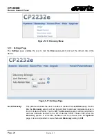
Страница 33: ...pen Here the user can add tags to the device in order to create shortcut buttons while searching for a system on the first selection screen of the panel Service This field displays the available SNMP services for the device The user can drag and drop a service from the Available Services column to the desired device s Service field Figure 5 15 Update System Window 5 3 DISCOVERY MENU The Discovery ...

Страница 34: ... parameter allows the user to enable or disable the Lock Discovery If set to On the Discovery system will not be permitted to add new hardware devices to the list of devices found If set to Off the Discovery system will be permitted to add new hardware devices to the list of devices found Please note when the Discovery system is set to On hardware can be removed from the Systems page It is recomme...

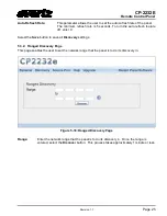
Страница 35: ...h feature off enter 0 Select the Save button to save all Discovery settings 5 3 2 Ranged Discovery Page This page enables the user to set the network range that the panel is to do its discovery in Figure 5 18 Ranged Discovery Page Range Enter the network range that the panel is to do its discovery in Once the range is entered select the Discover button This process takes approximately 1 minute or ...

Страница 36: ...Labels Page To import a device label follow the instructions outlined below 1 Select the Browse button and navigate to the appropriate csv file and then select the Open button 2 Once the file name is displayed in the field next to the Browse button select the Install button The panel must be restarted when a file is imported Click the Restart Panel Software button in the top right hand corner ...

Страница 37: ...VistaLINK Alarm Server This field enables the user to enter the VistaLINK Alarm Server network address Port This field enables the user to enter the port number the numerical input to map to Select the Save button to save all settings 5 4 SOURCE PROC MENU The Source Proc menu enables the user to create source service destination service and macro service mapping Figure 5 21 Source Proc Menu ...

Страница 38: ... which will be used if the device name and port are not provided d A Service created and saved on the CP 2232E panel 2 Select the plus sign to create a new mapping 3 Enter the PRECISE short name of the router device to map to in the Device Name field 4 Enter the port number the numerical input to map to in the Port field 5 Enter an Alias name for the router source Please note that this parameter i...

Страница 39: ...rt Figure 5 23 Destination Proc Page To create a new Destination Service Mapping please follow the numbered instructions in section 5 4 1 5 4 3 Macros Page The Macros page as illustrated in Figure 5 24 enables the user to map a Macro to an SNMP Service This will automatically fire the Macro on the VistaLINK Alarm Server when the Service is loaded Figure 5 24 Macros Page ...

Страница 40: ... When you are finished mapping the Macro be sure to click the Restart Panel Software link found at the top of each page 5 5 HELP MENU The Help menu enables the user to view panel and products information retrieve logs change preference settings and import export configurations Figure 5 25 Help Menu 5 5 1 Help Page Selecting the Help menu enables the user to view the current panel version product s...

Страница 41: ...number 5 5 1 2 Product Support The Product Support option provides a list of current product versions Figure 5 27 Product Support Tab Clicking the Product Versions text will reveal a list of currently supported products and their version numbers 5 5 1 3 Configuration The Configuration tab as illustrated in Figure 5 28 enables the user to export the panel s configuration settings ...

Страница 42: ... Revision 1 1 Figure 5 28 Configuration Tab Select the Export Configuration text and an Opening config cf dialog box will be appear which will prompt the user to open or save the configuration file Figure 5 29 Opening config cf Dialog Box ...

Страница 43: ...gs tab as illustrated in Figure 5 30 enables the user to retrieve configuration logs Figure 5 30 Logs Tab Select the Download Logs text and an Opening logs lf dialog box will appear which will prompt the user to open or save the log file Figure 5 31 Opening logs lf Dialog Box ...

Страница 44: ... and Classic Auto Select This parameter enables the user to enable or disable the Auto Select function If set to On a single item in a list will be automatically selected where applicable without having to use the Select button If set to No the Select button will need to be used in order to select an item from a list Dial Rotation This parameter enables the user to change the shaft encoders scroll...

Страница 45: ... and navigate to the appropriate configuration file and then select the Open button 4 Once the file name is displayed in the field next to the Browse button select the Install button 5 The panel must be restarted when a file is imported Click the Restart Panel Software button in the top right hand corner To export a configuration select the Export Configuration button An Opening config cf dialog b...

Страница 46: ...menu enables the user to upgrade the firmware on the CP 2232E panel Select the Upgrade menu and the Install Firmware page will open as illustrated in Figure 5 34 Figure 5 34 Install Firmware Page For instructions on how to upgrade the panel s firmware please refer to section 5 1 3 ...

Страница 47: ... click the Transfer button Restart the server to apply this canvas 2 Daily operation of the MVP to allow the CP 2232E control of a layout a Open an existing layout while connected in maestro and select the save as script option Assign a descriptive name and then click send you will need to do this with any layout you wish to appear on the CP 2232E 3 Set up the CP 2232E This setup should only have ...

Страница 48: ...Daily operation of the CP 2232e Directly using the panel a Select the MVP system from the CP2232E front panel by navigating to the appropriate system using the shaft encoders and soft keys b Once the list is generated select a display from the list and select OK c The layout that is currently loaded will be displayed and a list of layouts that the user can load will be provided Select one of the l...

Страница 49: ...232E This is done using the Systems Products menu 2 Select Systems Service Templates menu and create a Service Template that contains the controls required for the SNMP products Save changes 3 Select Systems Services menu and create a Service mapping of the Service Template to a specific Service that contains the appropriate frame card slot input information for the SNMP enabled product for contro...

Страница 50: ...adjust to accommodate the EQX Server parameters In the Name field enter a unique identifier name this name will appear on the panel Enter the IP address of the EQX server host into the IP field Enter the appropriate port into the Port field The default port is 8765 The user can also enter information into the Tags and Details fields Figure 6 4 Add EQX Server 4 Once the user has filled out all the ...

Страница 51: ...ss is simple Create SNMP services and then choose the routing device and source port to attach the service to In this way SNMP Services and therefore Terminal gear parameters can be accessed from within the EQX Server portion of the CP 2232E and users do not have to filter through long lists looking for the correct Service name For more information on Mapping please refer to section 5 4 ...

Страница 52: ...a quadrant The default button navigation pad will contain Src Dst Up Dwn Clear Next Src Level More and Take buttons Depending on the panel configuration the default button assignments may contain more or less then shown in Figure 7 1 7 1 SOURCE SRC BUTTON Figure 7 2 SRC Layout The SRC button when pushed will display a list of available sources in the Left display screen and the components that mak...

Страница 53: ... the CP 2232E will automatically filter the source list to display any source that matches the characters typed If a character is typed incorrectly the DEL button can be used to delete the characters The Left and Right buttons on the Left screen can be used to navigate the SRC Search box When the required source is highlighted the Enter button is used to confirm the choice and return the user to E...

Страница 54: ...y selected in the Eight Destination view The quadrant view in the bottom of the Left display will show the user where the destination will appear when returning to the Eight Destination view The Back button can be used to cancel the destination search and return to the Eight Destination view Figure 7 5 DST Keypad Display The Alpha Numeric button when pressed will allow the user to type the name of...

Страница 55: ...he destination search and return to the Eight Destination view 7 3 UP DOWN ARROWS Figure 7 6 Up Down Arrows Display The Destination navigation buttons allow the user to scroll Up or Down through the pages of destinations The Current Page and Total Number of Pages is displayed in the bottom right corner of each LCD screen The last destination page contains Dynamic Destinations The user can select a...

Страница 56: ...emote Control Panel Page 46 Revision 1 1 7 4 CLEAR NEXT SOURCE BUTTON Figure 7 7 Clear Next Source Button The Clear Next SRC button allows the user to clear the pending or preset source for a selected destination ...

Страница 57: ... is not shown the level is disabled Figure 7 9 Selecting the Video Button To enable or disable a level for a destination the user will push the associated level button on the panel If a level has been disabled the associated level button will turn Red and the Right screen will not show the Green X for that level The Left screen will display a breakaway icon for the destination If a level has been ...

Страница 58: ... associated level buttons will turn Green and the Right screen will show the Green X for those levels The Left screen will display a Green X icon for the destination if all levels are enabled The level state will not change if the user selects the Back button to return to the Eight Destination view Figure 7 11 Selecting the BREAK AWAY Button The Breakaway button when selected will each level indiv...

Страница 59: ... list of Profiles that have been assigned to the panel from MAGNUM A Profile contains sources destinations labels and categories These can be different on a per profile basis The Left and Right screens will display the list of available profiles for selection The left shaft encoder under each screen can be used to scroll through the list When the required Profile is highlighted the Select button i...

Страница 60: ...ormation on the Left screen and Level Source and Next Source information on the Right Screen The Back button can be used to return to the Eight Destination view Figure 7 15 Selecting the SRC INFO Button The SRC INFO button when selected with display the Source Name and Physical Port information for the source that is on the selected destination The Back button can be used to return to the Destinat...

Страница 61: ... will have circular blue arrows next to the green cross point icon in the top left corner of the destination quadrant Figure 7 17 Selecting the LOCK DST Button The LOCK DST button when pressed will toggle between Locking or Unlocking the selected destination A destination that is locked will display a Lock icon in the top right corner of the destination quadrant When a destination is locked no rou...

Страница 62: ...cted the destination or an Admin user can un protect the destination To view the owner of a protected destination select the INFO button The Back button can be used to return to the Eight Destination view Figure 7 19 Selecting the TIELINES Button The TIELINES button when selected will display all Tielines configured for MAGNUM system in the Left screen and the Right screen will show the source on ...

Страница 63: ...Numeric button when pressed will allow the user to type the name of the required source in the Left screen As the user types the CP 2232E will automatically filter the source list to display any source that matches the characters typed If a character is typed incorrectly the DEL button can be used to delete the characters The Left and Right buttons on the Left screen can be used to navigate the SR...

Страница 64: ...g the TOGGLE TAKE Button When in One Destination View the TOGGLE TAKE button can be used to toggle with each press between the Current Source and the Previous Source on the selected destination Figure 7 23 Selecting the SALVO Button The SALVO button when pressed will display a list of Salvos in the left screen that are available to the current profile active on the panel The left shaft encoder und...

Отзывы: