background image

CP-1024E 

Control Panel


4. 

FRONT PANEL CONTROL 

4.1. 

FRONT CONTROL PANEL 

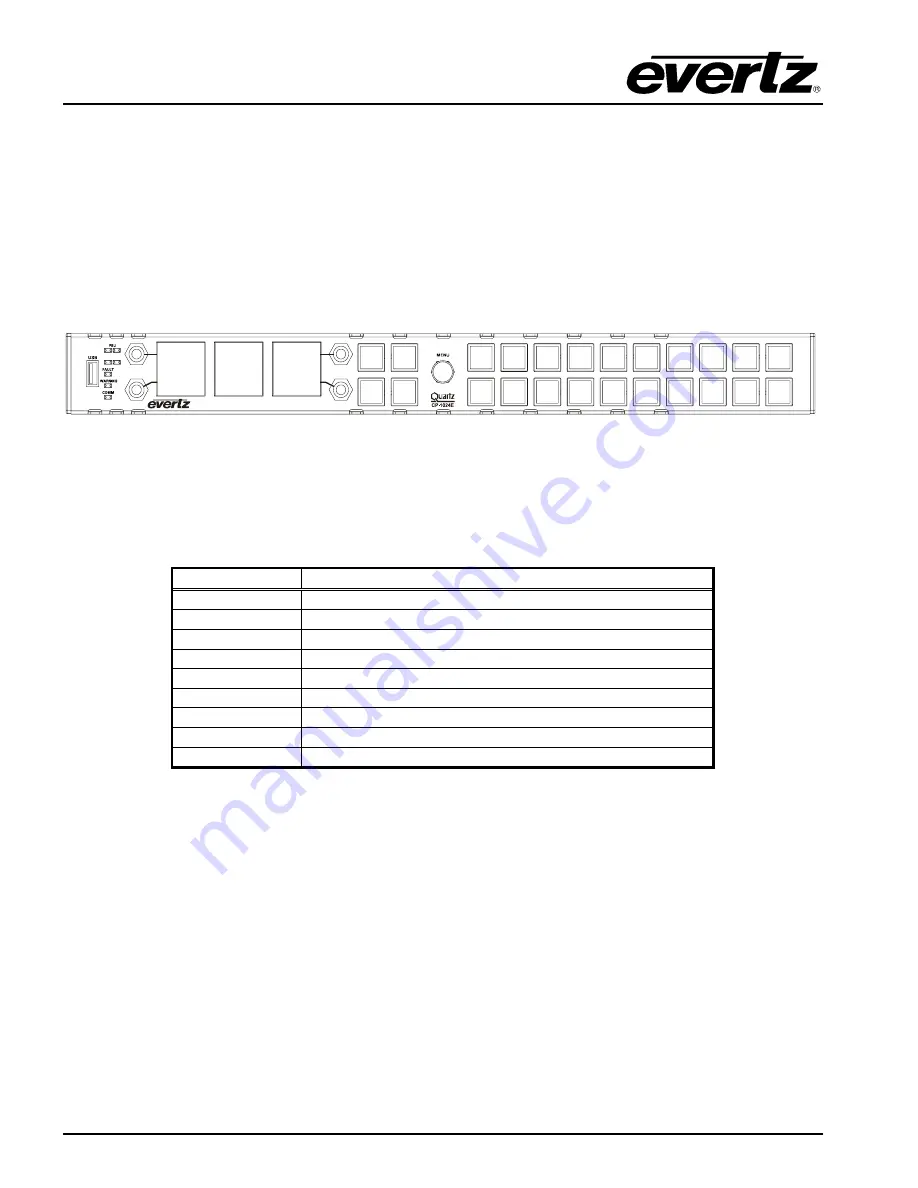
The CP-1024E has both rotary encoders and programmable LED buttons on its front panel. There are 5 
rotary shaft encoders and a total of 24 programmable LED buttons. Rotary encoders are used to 
access and adjust panel settings. There are three display windows which are used to display source, 
destination and level information.  


B1

B2

B3

B4

TL

BL

TR

BR


Figure 4-1: CP-1024E Front Control Panel  

 
Please note that the blue labels in Figure 4-1


will NOT be displayed on the front panel of your CP-

1024E device. The labels listed above are for reference purposes only when describing the panel 
controls in the following sections of the manual.  The following chart describes the label and function of 
the associated button.  
 

Labels Description 

TL 

Top Left Rotary encoder 

BL 

Bottom Left Rotary encoder 

TR 

Top Right Rotary encoder 

BR 

Bottom Right Rotary encoder 

Menu 

Menu Rotary encoder 

B1 

Top Left button in four button cluster 

B2 

Top Right button in four button cluster 

B3 

Bottom Left button in four button cluster 

B4 

Bottom Right button in four button cluster 

 
The rotary encoders are used to toggle through the menu items by rotating the knob clockwise (down) 
and counter-clockwise (up).  To select an item, toggle so that the menu item is highlighted in the first 
display window and then push in the 

Menu

 rotary encoder to make the selection. The sub-menu for the 

selected item will appear in the second display window. If further selection is required, use the 

Menu 

rotary encoder to toggle to the desired item and then push in the encoder to make your selection. The 
next sub-menu will appear in the third display window. Rotate the 

Menu

 encoder to toggle to a 

parameter value and then push in the encoder to move to the next selection. Once all the desired 
adjustments have been made, use the 

B2 

button to back out of each sub-menu. Each time the 

B2


button is pressed the user can back out another menu level until the main menu on the first LCD screen 
is the only list displayed.   
 

Page 6


Revision 1.1


Содержание CP-1024E

Страница 1: ...ersion 1 1 January 2011 The material contained in this manual consists of information that is the property of Evertz Microsystems and is intended solely for the use of purchasers of the CP 1024E Evertz Microsystems expressly prohibits the use of this manual for any purpose other than the operation of the device All rights reserved No part of this publication may be reproduced without the express w...

Страница 2: ...This page left intentionally blank ...

Страница 3: ...ird grounding prong The wide blade or the third prong is provided for your safety If the provided plug does not fit into your outlet consult an electrician for replacement of the obsolete outlet Protect the power cord from being walked on or pinched particularly at plugs convenience receptacles and the point where they exit from the apparatus Only use attachments accessories specified by the manuf...

Страница 4: ...IGITAL DEVICE OR PERIPHERAL This equipment has been tested and found to comply with the limits for a Class A digital device pursuant to Part 15 of the FCC Rules These limits are designed to provide reasonable protection against harmful interference when the equipment is operated in a commercial environment This equipment generates uses and can radiate radio frequency energy and if not installed an...

Страница 5: ...fered by Evertz in relation to this product is the Evertz standard limited warranty stated in the sales contract or order confirmation form Although every attempt has been made to accurately describe the features installation and operation of this product in this manual no warranty is granted nor liability assumed in relation to any errors or omissions unless specifically undertaken in the Evertz ...

Страница 6: ...CP 1024E Control Panel This page left intentionally blank Page ii Revision 1 1 ...

Страница 7: ...NTROL 6 4 1 FRONT CONTROL PANEL 6 4 2 FRONT STATUS LEDS 7 4 2 1 PSU LEDs 7 4 2 2 FAN LEDs 7 4 2 3 FAULT LED 7 4 2 4 WARNING LED 7 4 2 5 COMMS LED 7 4 3 MAIN MENU 7 4 3 1 Engineering Setup 8 4 3 1 1 Setting the IP Address of the Control Panel 8 4 3 1 2 Setting the Netmask 8 4 3 2 Setting the Broadcast Address 9 4 3 3 Setting the Gateway 9 4 3 3 1 Setting the Font Size 9 4 3 3 2 Setting the Dual PSU...

Страница 8: ...el 1 Figure 2 1 CP 1024E Rear Panel 2 Figure 4 1 CP 1024E Front Control Panel 6 Figure 5 1 CP2200e Main Screen 14 Figure 5 2 Uploading Progress Window 15 Figure 5 3 Upgrade the CP1024e 16 Figure 5 4 Successful Firmware Upgrade 17 Figure 5 5 CP 1024E Configuration Interface in EQX Server 18 Figure 5 6 Type Drop Down Menu 19 Figure 5 7 Populated Control Panel Interface 20 Figure 5 8 Moving Buttons u...

Страница 9: ...ions such as level selection lock etc The CP 1024E is a very sophisticated and advanced panel that allows the user to create a very powerful and simple interface for your entire system It is ideal for applications where a 1RU panel design with more LCD screen area is critical based on number of sources destinations or levels to control This makes it perfect in many different environments including...

Страница 10: ...ck push buttons to override the router 2 1 4 USB Control This USB 2 0 Port is used for USB based firmware upgrades of the CP 1024E 2 1 5 Ethernet Connection The cards use 10Base T 10 Mbps 100Base TX 100 Mbps twisted pair Ethernet cabling systems When connecting for 10Base T systems category 3 4 or 5 UTP cable as well as EIA TIA 568 100Ω STP cable may be used When connecting for 100Base TX systems ...

Страница 11: ...y as a means of checking that the link is working correctly When the network is idle the devices also send a link test signal to one another to verify link integrity The rear panel is fitted with two LEDs to monitor the Ethernet connection 1000 This Amber LED is ON when a 100Base TX link is last detected The LED is OFF when a 10Base T link is last detected the LINK LED is ON Upon power up the LED ...

Страница 12: ...rning the fastening nut CAUTION TO REDUCE THE RISK OF ELECTRIC SHOCK GROUNDING OF THE GROUND PIN OF THE MAINS PLUG MUST BE MAINTAINED 2 2 MOUNTING The CP 1024E is equipped with rack mounting angles and fits into a 19 inch by 3 5 inch by 1 75 inch 483 mm x 89 mm x 45mm rack space Cooling is achieved by fan assisted convection Air is drawn into the right side of the chassis and expelled as hot air f...

Страница 13: ... 240V AC 50 60Hz or 12V DC 3A Power 15 Watts Fuse Rating 250V 2A time delay 3 1 3 Physical Height 1 75 45mm 1RU standard rack height Width 19 483mm rack mount Depth 3 5 89mm not including connectors Weight 3lbs 1 36kg Operating Temp 0 40 C 3 1 4 Compliance Safety ETL Listed complies with EU safety directives EMI RFI Complies with FCC Part 15 Class A regulations Complies with EU EMC directive Revis...

Страница 14: ...u Rotary encoder B1 Top Left button in four button cluster B2 Top Right button in four button cluster B3 Bottom Left button in four button cluster B4 Bottom Right button in four button cluster The rotary encoders are used to toggle through the menu items by rotating the knob clockwise down and counter clockwise up To select an item toggle so that the menu item is highlighted in the first display w...

Страница 15: ...when a serious internal fault has been detected within the CP 1024E 4 2 4 WARNING LED This LED will be illuminated red when a non critical internal fault error has been detected within the CP 1024E 4 2 5 COMMS LED Not implemented at this time 4 3 MAIN MENU To enter the setup menu of the CP 1024E control panel press and hold the top TL and bottom BL rotary encoders on the far left side of the panel...

Страница 16: ...t setting 4 3 1 1 Setting the IP Address of the Control Panel The IP Addr menu item is used to set the IP address of the CP 1024E control panel The IP address is displayed in the following format aaa bbb ccc ddd Use the Menu rotary encoder to change the IP Address values To change the value rotate the encoder clockwise or counter clockwise To move to the next three digits of the address push in th...

Страница 17: ...gateway address is displayed in the following format aaa bbb ccc ddd Use the Menu rotary encoder to change the Gateway Address values To change the value rotate the encoder until you have highlighted the desired value To move to the next three digits of the address push the encoder in and the next set of numbers will be highlighted Once the Gateway address is set use the B2 button to return to the...

Страница 18: ...3 3 4 Revert Changes The Revert Changes option can be used when changes have been made in the setup menu but the user no longer wants to apply these changes and wishes to revert to the original settings As long as the changes have not been saved the user can revert back to the original settings by toggling to the Revert Changes option and pushing in the rotary encoder to revert back to the previou...

Страница 19: ...button push one of the buttons and the flashing test should stop The user can now test the functionality of each individual button Pressing a button should illuminate it and key information for that button will be shown in the second display screen For example Key Test Btid 4 down 1 indicates button ID 4 has been pushed down 1 time Btid 4 up 1 indicates button ID 4 has been depressed 1 time To exi...

Страница 20: ...ated When set to OK the green PSU LED will be illuminated AUX FAIL OK When set to FAIL the red FAN LED will be illuminated When set to OK the green FAN LED will be illuminated FAULT ON OFF When set to ON the FAULT LED will illuminate red When set to OFF the FAULT LED will not be illuminated WARNING ON OFF When set to ON the WARNING LED will illuminate orange When set to OFF the WARNING LED will no...

Страница 21: ...d below or by referring to section 4 3 1 1 1 To identify the IP address hold down the top and bottom left rotary encoders TL and BL for approximately 6 seconds 2 When the main engineering menu appears toggle to the SETUP menu and push in the Menu rotary encoder 3 Next select the IP Addr option and push in the Menu rotary encoder once again Obtain the IP address which will appear on the third displ...

Страница 22: ...ar as shown in Figure 5 1 Figure 5 1 CP2200e Main Screen 2 Using the Browse button navigate to the img firmware file that you wish to update Example up 1 1 0 img 3 The user can load the upgrade file to the CP 1024E control panel by pressing the Upload to CP1024e button that appears once the file is selected The firmware on the panel will now be updated and an uploading message will be displayed in...

Страница 23: ... Figure 5 2 Uploading Progress Window 4 When the firmware has been successfully uploaded click on the Upgrade the CP1024e button as shown in Figure 5 3 Selecting this button will upgrade the firmware file using the img file you previously loaded ...

Страница 24: ...e 5 3 Upgrade the CP1024e 5 Once the panel has been upgraded a message will be displayed to inform the user of a successful upgrade as shown in Figure 5 4 6 In order for firmware changes to take effect the user must restart the CP 1024E control panel ...

Страница 25: ...CP 1024E Control Panel Revision 1 1 Page 17 Figure 5 4 Successful Firmware Upgrade ...

Страница 26: ...Web Configuration Tool 1 Launch your EQX server Web Configuration Tool in a web browser and log in to the server 2 Navigate to the Interfaces menu and then select CP 1024E from the list 3 An Interface Layout CP 1024E page will appear enabling the user to apply button key settings to the panel Figure 5 5 CP 1024E Configuration Interface in EQX Server ...

Страница 27: ...ny other interface except the one that is protecting the destination Level Toggles the level on off to affect possible breakaways on subsequent takes Displays the level name Level Mode Changes the level mode Locks Allows access to the locks functionality Not Used Defines the button as not being used Multi Function This button allows for a combination of Add or Append String Numeric or Level assign...

Страница 28: ...changes made on the interface to the actual CP 1024E panel the user must select the Send button When the Send button is selected the button assignments will be transferred to the physical CP 1024E control panel Figure 5 9 Control Buttons 8 If the user has made changes and wishes to revert to the original panel layout select the Revert button to clear the panel and switch back to its original confi...

Отзывы: