background image

7880IPG-NAT Series 

High Density Network Address Translator


Revision 2.1


Page - 11 

2.5. 

CONFIGURING SNMP SETTINGS 

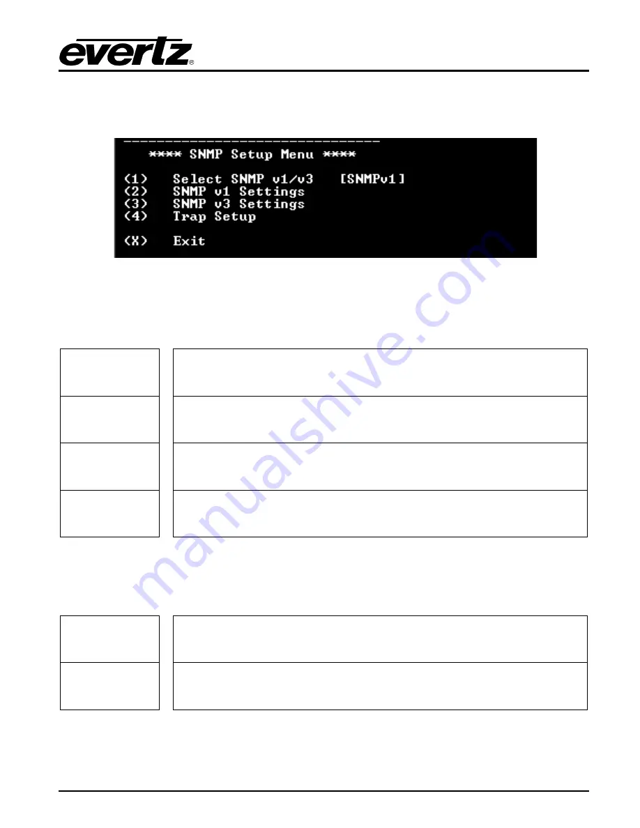
From the Main Menu, select option (2) 

SNMP Setup

.  


Figure 2-6: SNMP Setup Menu 


2.5.1.  SNMP Setup 

In the

 SNMP Setup

 menu, there are four submenus to choose from:  


SNMP Version 
Setup 


This menu item identifies which of the two version of SNMP will be used to 
communicate to the device. 

SNMP V1 
Setup 


This menu item contains setup information for SNMP version 1 related 
configurations. 

SNMP V3 
Setup 


This menu item contains setup information for SNMP version 3 related 
configurations. 

Trap Setup 


This menu item allows the user add or remove trap destinations. 


2.5.1.1.  SNMP V1 Setup 

In the 

SNMP V1 Setup

 menu, three parameters are configured: 


Read 
Community 
String 


Factory default “public” (No changes required. However, if these settings are 
changed, the manager must have the identical settings. Otherwise no 
communication will occur between the 7880IPG-NAT and the manager.) 

Read/Write 
Community 
String 


Factory default “private” (No changes required. However, if these settings are 
changed, the manager must have the identical settings. Otherwise no 
communication will occur between the 7880IPG-NAT and the manager.) 

 
Once the 

SNMP V1 Setup

 parameters have been configured, exit 

SNMP V1 Setup

 by pressing 

X

 then 

<Enter>


Содержание 7880IPG-NAT Series

Страница 1: ...at is the property of Evertz Microsystems and is intended solely for the use of purchasers of the 7880IPG NAT series product Evertz Microsystems expressly prohibits the use of this manual for any purpose other than the operation of the 7880IPG NAT series product Due to on going research and development features and specifications in this manual are subject to change without notice All rights reser...

Страница 2: ...This page left intentionally blank ...

Страница 3: ...ird grounding prong The wide blade or the third prong is provided for your safety If the provided plug does not fit into your outlet consult an electrician for replacement of the obsolete outlet Protect the power cord from being walked on or pinched particularly at plugs convenience receptacles and the point where they exit from the apparatus Only use attachments accessories specified by the manuf...

Страница 4: ... Class A digital device pursuant to Part 15 of the FCC Rules These limits are designed to provide reasonable protection against harmful interference when the equipment is operated in a commercial environment This equipment generates uses and can radiate radio frequency energy and if not installed and used in accordance with the instruction manual may cause harmful interference to radio communicati...

Страница 5: ... 11 3 TECHNICAL SPECIFICATIONS 15 3 1 SFP MODULES 15 3 2 IP NAT AND MC IN MC NAT MODES 15 3 3 VLAN BASED NAT 15 3 4 PORT BASED NAT 15 3 5 ELECTRICAL 15 3 6 COMPLIANCE 15 3 7 PHYSICAL NUMBER OF SLOTS AND ENCLOSURES 15 4 WEB INTERFACE 17 4 1 SYSTEM TAB 18 4 2 FLOW TABLE IP NAT MODE MC IN MC NAT MODE 22 4 2 1 IP NAT Mode and MC In MC NAT Mode Block Diagrams 24 4 3 IP NAT CONTROL TAB 25 4 4 MC IN MC N...

Страница 6: ... Flow Table IP NAT MC in MC NAT Modes Tab 22 Figure 4 5 IP NAT Mode Block Diagram 24 Figure 4 6 MC In MC NAT Mode Block Diagram 24 Figure 4 7 WebEASY IP NAT Control Tab 25 Figure 4 8 WebEASY Multicast In Multicast NAT Control 27 Figure 4 9 Port Based NAT Mode Block Diagram 28 Figure 4 10 WebEASY Port Based NAT Control Tab 29 Figure 4 11 VLAN Based NAT Mode Block Diagram 32 Figure 4 12 WebEASY VLAN...

Страница 7: ...nor for the rights of third parties which may be affected in any way by the use thereof Any representations in this document concerning performance of Evertz products are for informational use only and are not warranties of future performance either expressed or implied The only warranty offered by Evertz in relation to this product is the Evertz standard limited warranty stated in the sales contr...

Страница 8: ...7880IPG NAT Series High Density Network Address Translator Page iv Revision 2 1 This page left intentionally blank ...

Страница 9: ...flexibility for LAN WAN interfacing The 7880IPG NAT 6 10GE2 provides the following four modes of operation The One to One or IP NAT Mode allows multicast IP streams from one network to be translated to different unicast multicast IP addresses on a flow by flow basis up to 128 unique flows per processing core Address translation is available in both directions while an optional Packet Replication f...

Страница 10: ...sed NAT for flows based on VLAN tagged datagrams o Port based NAT for encapsulating all traffic on a physical port WAN side Port Aggregation and Demux in all modes Point to point and multi point signal distribution contribution inside the facility Operates over a IP MPLS VPLS core network In band Management Management Traffic transport over Multicast Full integration with VistaLINK PRO and Magnum ...

Страница 11: ...E Port LAN Side LAN RX Network Address Translation Optional Encap MC in MC mode only Packet Accumulation Port Mode Only Optional Encap Bandwidth Capping Port Mode Only Optional WAN to LAN or De Encap Direction LAN to WAN or Encap Direction IP NAT MC in MC NAT Modes VLAN Port Modes IP NAT Mode MC in MC NAT VLAN Port Modes IP NAT MC in MC NAT Modes VLAN Port Modes Figure 1 1 Single NAT Core Block Di...

Страница 12: ...7880IPG NAT Series High Density Network Address Translator Page 4 Revision 2 1 Figure 1 3 WAN Side Port Aggregation and Demux available in all modes ...

Страница 13: ...companion rear plate Figure 2 1 provides an illustration of the 7880IPG NAT rear plate Figure 2 1 7880IPG NAT 6 10GE Rear Plate 1GigE or 10GigE Input Output There are 12 SFP bi directional connections used for the 1GE or 10GE input and output CTRL There is one RJ45 Connector used for communications with a web browser using WebEASY WAN Connections LAN Connections ...

Страница 14: ...e 2 2 for the current RJ 45 standards AT T 258A EIA TIA 568A or EIA TIA 568B colour coding listed Also refer to the notes following the table for additional wiring guide information Figure 2 2 RJ 45 Connector Pin Out Locations Pin 1 Pin Signal EIA TIA 568A AT T 258A or EIA TIA 568B 10BaseT or 100BaseT 1 Transmit White Green White Orange X 2 Transmit Green White or White Orange White or Orange X 3 ...

Страница 15: ... established a valid linkage to its switch and whether the module is sending or receiving data This LED will be ON when the module has established a good link to its supporting switch This gives you a good indication that the segment is wired correctly The LED will BLINK when the module is sending or receiving data The LED will be OFF if there is no valid connection 2 2 CARE AND HANDLING OF OPTICA...

Страница 16: ...board using the rainbow coloured serial cable provided Now insert the 7880IPG NAT card into the corresponding front slots ensuring the card lines up with the slot runners on the bottom and the top of the chassis Push the card firmly into the slot ensuring that when it mates with the rear card it has been firmly pushed into a seated position Do not connect any cables to the rear plate failure to do...

Страница 17: ... Menu 1 Network Setup This sub menu enables the user to configure the control network settings for the card Configuring this sub menu allows the user to access the card through the User Interface 2 SNMP Setup This sub menu enables the user to configure the Simple Network Management Protocol settings In this menu you can set or remove the SNMP trap IP address and the SNMP Read and Set community str...

Страница 18: ...uring that the IP address is not already in use on the network 2 Now select option 2 Set Netmask and configure the correct subnet mask for your network 3 If required also configure option 3 Set Gateway and 4 Set Broadcast Address 4 Enter X to go one level up 5 From the main menu in Figure 2 5 enter X to save and apply settings Power Cycle the 7880IPG NAT to ensure all changes are applied and saved...

Страница 19: ... version 3 related configurations Trap Setup This menu item allows the user add or remove trap destinations 2 5 1 1 SNMP V1 Setup In the SNMP V1 Setup menu three parameters are configured Read Community String Factory default public No changes required However if these settings are changed the manager must have the identical settings Otherwise no communication will occur between the 7880IPG NAT an...

Страница 20: ...Authentication will be automatically set back to NONE The password must be at least 8 characters long Use Privacy Default is NONE Options are NONE AES or DES Use Privacy will encrypt incoming and outgoing messages Encryption Password If Use Privacy is not set to NONE then this field is mandatory otherwise Use Privacy will be automatically set back to NONE The password must be at least 8 characters...

Страница 21: ...tribution list For example selecting this option reveals the list of IP addresses with the prompt to remove one from the list Trap 1 192 168 1 76 Trap 2 192 168 8 140 Remove trap 2 Show All Trap Destinations Displays a list of all entered SNMP trap server IP addresses For example Trap 1 192 168 1 76 Trap 2 192 168 8 140 Trap 3 192 168 8 112 Once the SNMP V1 Setup parameters have been configured ex...

Страница 22: ...7880IPG NAT Series High Density Network Address Translator Page 14 Revision 2 1 This page left intentionally blank ...

Страница 23: ... per direction 3 3 VLAN BASED NAT 768x VLAN ID flows capacity per direction 3 4 PORT BASED NAT 6x Physical flows capacity 3 5 ELECTRICAL Power 40W Voltage 12VDC EMI RFI Complies with FCC Part 15 Class AEU EMC directive 3 6 COMPLIANCE Electrical Safety Power supply UL listed complies with CE Low Voltage Directive EMI RFI Complies with FCC Part 15 Class A EU EMC directive 3 7 PHYSICAL NUMBER OF SLOT...

Страница 24: ...7880IPG NAT Series High Density Network Address Translator Page 16 Revision 2 1 This page left intentionally blank ...

Страница 25: ...accessed by entering the IP address of the control port of the 7880IPG NAT into the address bar of an Internet web browser Refer to section 2 4 for setting the network configurations When first visiting the 7880IPG NAT web interface the user will be asked to enter a Login and Password Enter root for Password and evertz for Login to get administrator privileges When viewing only the configurations ...

Страница 26: ...e 4 2 WebEASY System Tab Part 1 Processing Cores Configurations for Core 1 to Core 6 Mode of Operation Within this drop down menu the user can configure the desired mode of operation for the 7880IPG NAT The NAT can be set to IP NAT mode MC In MC NAT IP NAT mode Port Based NAT mode VLAN Based NAT mode ...

Страница 27: ...er to set the Gateway Address of the corresponding Ethernet port a reboot is required after modifying this field Data Port Traffic Monitoring For each of the 12 Data ports the following parameters can be monitored Link Speed This monitor will automatically detect the link speed of the SFP module installed Link Status This field displays the physical link status of the associated data port as eithe...

Страница 28: ...vel dbm This field displays the receiving power level on the SFP SFP TX Power Level dbm This field displays the transmitting power level for the SFP Global Traffic Monitoring Total WAN Ports Rx Bandwidth Mbps This parameter displays the total received bandwidth for all WAN Ethernet ports Total WAN Ports Tx Bandwidth Mbps This parameter displays the total sent bandwidth for WAN Ethernet ports Total...

Страница 29: ...s This parameter displays the total sent bandwidth for LAN Ethernet ports Temperature Monitoring FPGA Temperature This monitor will display the temperature of the FPGA System System Reboot This button allows the user to reboot the 7880IPG NAT module doing this will result in the connection being lost temporarily ...

Страница 30: ... applies to the flows for IP NAT Mode and MC In MC NAT Mode Figure 4 4 WebEASY Flow Table IP NAT MC in MC NAT Modes Tab There is up to 128 transport streams that can be specified to be configured based on its multicast address and is sectioned into flow groups Each flow group will display eight flows for configuration There are 16 flow groups in total ...

Страница 31: ... Destination UDP Port number to be received Input Bit rate This monitor will display the bit rate of the streams that are being received in kbps WAN to LAN Input Flow Configuration NAT Cores 1 to 6 Mode This control allows the user to enable De Encap NAT or disable the input associated with that flow Only when in MC in MC mode the module will de encapasulate Input Destination IP Address also used ...

Страница 32: ...G NAT Series High Density Network Address Translator Page 24 Revision 2 1 4 2 1 IP NAT Mode and MC In MC NAT Mode Block Diagrams Figure 4 5 IP NAT Mode Block Diagram Figure 4 6 MC In MC NAT Mode Block Diagram ...

Страница 33: ...25 4 3 IP NAT CONTROL TAB The IP NAT Control section applies to IP NAT Mode The LAN to WAN configuration also applies to MC in MC mode if Modify option is chosen Note NAT cores will operate only in the selected NAT Mode under the System tab Figure 4 7 WebEASY IP NAT Control Tab ...

Страница 34: ...headers while Modify enables changes to the headers Source IP Address This control is used in NAT mode to configure the output header with the desired source IP address Source UDP Port This control is used in NAT mode to configure the output header with the desired source UDP Port Destination MAC This control is used to enter the Destination MAC address Destination IP Address This control is used ...

Страница 35: ...s used to configure the output header with the desired source IP address when the output is being encapsulated Source UDP Port This control is used to configure the output header with the desired source UDP Port when the output is being encapsulated Destination IP Address This control is used to configure the output header with the desired destination IP address when the output is being encapsulat...

Страница 36: ...ysical port on a port by port basis There is no multicast or VLAN Tag filtering All traffic on that physical LAN port is encapsulated out to the WAN and de encapsulated in the reverse direction This mode provides a Bandwidth Capping feature such that network operators can ensure that links do not over subscribe their contribution limits to a WAN Figure 4 9 Port Based NAT Mode Block Diagram ...

Страница 37: ...rce IP Address This control allows the user to set the physical source IP address of the incoming traffic Source UDP Port This control allows the user to set the physical source UDP port of the incoming IP traffic Destination MAC This control is used to configure the output header on the encapsulation with the desired Destination MAC address Destination IP Address This control is used to configure...

Страница 38: ...nts to Note 1 MTU is a hard limit while MAX LATENCY is a soft limit 2 If LATENCY is set too low output packets will be much smaller than MTU But if LATENCY is set very high there is no danger of output packets exceeding MTU Packets will always be less than MTU Deciding Values 1 Set MTU to whatever max packet length or slightly less that your network can tolerate for example 5000 bytes 2 How long d...

Страница 39: ...r to enable or disable the input stream which is going to be decapsulated Input Destination IP Address This control allows the user to set the IP address of the packet to be received Input Destination UDP Port This control allows the user to set the UDP Port number to be received Input Bit rate This monitor will display the bit rate coming in on the port ...

Страница 40: ...owever flows are based on VLAN Tags rather than unicasts multicasts alone Up to 128 unique flows can be configured per processing core with independent encapsulation headers Figure 4 11 VLAN Based NAT Mode Block Diagram Each VLAN flow must have a unique Tag value Two or more flows cannot share the same VLAN Tag because there is no Packet Replication in VLAN Mode VLAN Mode does not support nested V...

Страница 41: ...will display 16 flows for configuration There are eight flow groups in total LAN to WAN Input Configuration For cores 1 to 6 and flows 1 to 128 Mode This control allows the user to enable the associated input stream for encapsulation VLAN ID This control allows the user to assign a VLAN ID to the associated flow incoming packets of the flow with the specified VLAN ID will then be encapsulated Inpu...

Страница 42: ... desired destination IP address Destination UDP Port This control is used to configure the output header encapsulation with the desired destination UDP Port number WAN to LAN De Encapsulation Configuration For cores 1 to 6 and flows 1 to 128 Mode This control allows the user to enable the associated input stream which is going to be de encapsulated Input Destination IP Address This control allows ...

Страница 43: ...ate their Tx traffic to a single WAN Port Correspondingly Rx traffic from that WAN port is distributed to all contributing processing cores In the figure above Cores 1 6 are configured to aggregate their traffic to WAN Port 1 A given processing core cannot contribute its Tx traffic to more than one WAN port Correspondingly a given processing core cannot receive traffic from more than one WAN port ...

Страница 44: ...ts Link Status For SFP 1 to 12 Port Link This monitor will display green when a valid link has been established or red when a link has been disconnected 4 9 CONFIGURATION MANAGEMENT TAB The Configuration Management tab allows the user to export edit and import each mode in a CSV file format The CSV file is useable in Microsoft Excel and allows for easy editing saving and uploading file using the B...

Страница 45: ...Login and Password Enter root for Password and evertz for Login On the top of the web page for the 7880IPG NAT there is a tab labeled Upgrade The Upgrade tab is used to check current firmware version and upload the latest firmware Figure 5 1 WebEASY Upgrade Button on Top Menu Bar Selecting the Upgrade tab will take you to Figure 5 2 where the current firmware version is shown Should the firmware v...

Страница 46: ...Figure 5 2 WebEASY Firmware Upgrade Menu Click Choose File and browse to locate image file Once selected click Open to advance to next step Click Upgrade and watch progress bar for status Once completed the device will automatically restart Figure 5 3 WebEASY Firmware Upgrade Menu ...

Отзывы: