background image


4-36 


To-and-fro tour mode: Press Shift + Tour to run a to-and-fro tour. The system will 

ask you to enter the tour number you would like to run, and starts the tour after 

pressing Enter. To preset a tour before running it is necessary. 


Note: The difference between the One-way tour mode and To-and-fro tour mode is that 

the return modes are different. For example: There is a tour with 3 preset positions 1, 2 

and 3. The camera runs 1

2

3

1

2

3 in the One-way tour mode, and 1

2

3

2

1 in 

the To-and-fro tour mode. 


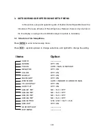
4.5.  Alarm Link to a Position/Tour 

    The Outdoor/Indoor Speed Dome has 4 alarm inputs that can be set to link to a position 

or a tour when an alarm is triggered. 
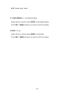
 

Set an alarm link: 

Press 

F1 to set an alarm link. Enter the alarm number, and then press Enter

Switch the Joystick up/down to select a position or a tour, enter a position or tour 

number, and then press 

Enter to confirm the alarm link setting. 


Delete an alarm link: 

            Press 

Clr + F1 to delete a link of alarm to position/tour. 


4.6.  Other operations 

The Outdoor/Indoor Speed Dome can work with a DVR that has PTZ control 

functions, and a matching protocol. The available control functions depend on 

different DVRs. 

The Outdoor/Indoor Speed Dome can work with a keyboard that has PTZ control 

functions, and a matching protocol. The available control functions depend on 

Содержание Speed Dome EPTZ1000

Страница 1: ...EPTZ1000 Outdoor Speed Dome EPTZ500 Indoor Speed Dome USER MANUAL Date Sep 26th 2005 ...

Страница 2: ...peed Dome Connection 1 11 1 5 Outdoor Indoor Speed Dome Quick Operation Guide Work with Multi Function Keyboard Controller 1 12 2 OUTDOOR INDOOR SPEED DOME INSTALLATION 2 13 2 1 Packing List 2 13 2 2 Cable Needed 2 13 Power Cable 2 13 Video Cable 2 14 Control Cable 2 14 Alarm Cable 2 14 2 3 Initial Setup 2 14 2 3 1 Address Setting 2 15 2 3 2 Communication Protocol Setting 2 18 2 3 3 Transmission S...

Страница 3: ...e adapter 2 28 2 5 3 Corner mount 2 28 2 5 4 Multi Function Keyboard Controller 2 28 3 OUTDOOR INDOOR SPEED DOME SETUP MENU 3 29 3 1 Structure of the Setup Menu 3 29 3 1 1 Camera Setup Menu 3 30 4 OUTDOOR INDOOR SPEED DOME FUNCTION SETUP AND OPERATION 4 34 4 1 Manual Control Mode 4 34 4 2 Auto Pan Mode 4 34 4 3 Position Setting 4 34 4 4 Tour Mode 4 35 4 5 Alarm Link to a Position Tour 4 36 4 6 Oth...

Страница 4: ...1 3 ...

Страница 5: ...ance function makes the shades of color more natural in different light conditions BLC Backlight Compensation function makes objects clear in a high illumination background Color B W images auto switching to enhance the sensitivity in a low light condition or at night Furthermore the micro control unit enables camera a nimble and exact movement from minimal 0 01 sec to maximal 360 sec It can go to...

Страница 6: ...puts and 1 alarm output All of the features make the intelligent high speed dome camera works for a wide range and demanding application such as banks airports stations casinos streets of cities intelligent buildings and etc ...

Страница 7: ... Control speed auto adjusted according to zoom length changing Auto Pan 2 points scanning Can set freely Auto Pan speed 1 239 grade available Dwell time 2 points 1 239 second available Preset Positions 192 positions Running to position speed 1 239 grade available 0 1º s 360º s Dwell time at preset position 1 60s available Tour 16 group Tour point per group 16 preset positions Fan Heater outdoor mo...

Страница 8: ...put BNC Dimension 220 W x 310 H mm Weight 3 2kg 1 3 Feature 1 3 1 Profile of Outdoor and Indoor Speed Dome Outdoor Speed Dome Wall Mount Bracket Housing Inner Housing M5 Bolt Hex x3 M3 Bolt x3 BNC Cable Power Cable RS485 Cable Connection Bus Bulb Mechanical Part Camera Module Control board Base PCB board ...

Страница 9: ...1 8 Indoor Speed Dome Housing Clip BNC Cable Power Cable RS485 Cable Connection Bus Bulb Mechanical Part Camera Module Control board Base PCB board Ceiling Button ...

Страница 10: ...names are marked on the board in white text The details of the alarm connector JP5 are shown on the APPENDIX A For Outdoor Speed Dome JP1 JP3 and JP6 that are two pin connectors on the base board need to be taken off during installation JP1 and JP3 are connectors for heater and they can be switched JP6 is a fan controller connector that turns on off of the fan The 3 cables are too short to be conn...

Страница 11: ...ndoor Speed Dome Control Board The PCB board with two dipswitches is the control board of speed dome The two switches are used to set address protocol Baud Rate video format and terminator resistance SW1 ON 1 2 3 4 5 6 7 8 CPU ON 1 2 3 4 5 6 7 8 SW2 ID1 ID2 ID3 ID4 ID5 ID6 ID7 ID8 Protocol BAUD ...

Страница 12: ...Dome Connection Alarm 1 Alarm 4 Alarm 3 Alarm 2 GROUND RS485 Tx RS485 Tx 24V AC 110V AC Video Out POWER 24V AC 3 5 A BNC 1 0Vpp 0 2V 75 RS485 Control Line 4 ALARM INPUTS Adapter Ω Outdoor Indoor Speed Dome ALARM OUTPUTS N C N O COM ...

Страница 13: ...Connect a video cable from Outdoor Indoor Speed Dome to a monitor 3 Connect the power to the Outdoor Indoor Speed Dome and a Multi Function Keyboard Controller After the speed dome finishes the self test mode you can start to operate the speed dome via the keyboard To operate the Outdoor Indoor Speed Dome IRIS Focus F Zoom In N Out UP DOWN LEFT RIGHT Zoom IN Zoom OUT 1 Shift the Joystick up down o...

Страница 14: ...tail accessories list below Housing x1 Bulb x1 Mechanical part with a camera module x1 Wall mount bracket x1 Adapter x1 Accessory packet Glove x2 M5 Hex Allen wrench x1 Pin connector x1 M5 screw Hex x3 for wall mount bracket fixing M3 screw x3 for bulb fixing Anchor nut and wall mount screw x4 2 2 Cable Needed Power Cable An adapter with 24V AC 3 5A output provides the power to the speed dome An e...

Страница 15: ...ed as a control cable Alarm Cable An alarm cable is not included in the packing list A suitable wire can be used as an alarm cable 2 3 Initial Setup Initial setup includes dome address communication protocol transmission speed video format and terminator resistance settings All of the settings should be confirmed before the dome is installed The control related setting that is address communicatio...

Страница 16: ...d of the address and there are 256 addresses can be selected 0 255 28 256 It also means that there up to 256 dome cameras can cascade on the RS485 bus The dipswitch setting and the indicated address are represented in the following chart Note The factory default address is 1 Notice Please make sure the power is off before setting and restart the speed dome to enable a new value after changing SW1 ...

Страница 17: ...ess Switch Address Switch Address Switch Address Switch Address Switch Address ON 1 2 3 4 5 6 7 8 Switch Address 65 ON 1 2 3 4 5 6 7 8 66 ON 1 2 3 4 5 6 7 8 67 ON 1 2 3 4 5 6 7 8 68 ON 1 2 3 4 5 6 7 8 69 ON 1 2 3 4 5 6 7 8 70 ON 1 2 3 4 5 6 7 8 71 ON 1 2 3 4 5 6 7 8 72 ON 1 2 3 4 5 6 7 8 73 ON 1 2 3 4 5 6 7 8 74 ON 1 2 3 4 5 6 7 8 75 ON 1 2 3 4 5 6 7 8 76 ON 1 2 3 4 5 6 7 8 Switch Address 77 ON 1 ...

Страница 18: ... 191 Switch Address Switch Address Switch Address Switch Address Switch Address Switch Address ON 1 2 3 4 5 6 7 8 Switch Address 193 ON 1 2 3 4 5 6 7 8 194 ON 1 2 3 4 5 6 7 8 195 ON 1 2 3 4 5 6 7 8 196 ON 1 2 3 4 5 6 7 8 197 ON 1 2 3 4 5 6 7 8 198 ON 1 2 3 4 5 6 7 8 199 ON 1 2 3 4 5 6 7 8 200 ON 1 2 3 4 5 6 7 8 201 ON 1 2 3 4 5 6 7 8 202 ON 1 2 3 4 5 6 7 8 203 ON 1 2 3 4 5 6 7 8 204 ON 1 2 3 4 5 6...

Страница 19: ...d dome to enable a new value after changing Set all of protocol switches to ON the Outdoor Indoor Speed Dome will enter a self test mode 2 3 3 Transmission Speed Setting Baud Rate Setting The 4th and 5th bits of the SW2 on the PCB board are used to set the Baud Rate The default baud rate setting is 9600 ON 1 2 3 4 5 6 7 8 SW2 Protocol Baud Rate PAL NTSC Maching Resistance ON 1 2 3 4 5 6 7 8 9600 B...

Страница 20: ... the power is off before setting and restart the speed dome to enable a new value after changing 2 3 5 RS 485 Bus Terminator Resistance For central controlling the terminator resistance should be set for the device that is the furthest one away from the controller The 8th bit on the SW2 is a switch to enable or disable the terminator resistance When it is switched ON the BUS terminator resistance ...

Страница 21: ...Resistance ON Note When the dome is out of control or does not work under control well try to switch the terminator resistance ON Notice Please make sure the power is off before setting and restart the speed dome to enable a new value after changing ...

Страница 22: ...selected installation location is suitable for the speed dome 2 4 2 Outdoor Dome Camera Wall Mount Installation Notice Installation location that is a wall a pole or a ceiling needs to support above five times the total weight of the camera assembly about 16 kg to avoid shaken images and dropping 1 Set wall mount bracket on the wall Mark the center of the holes on the wall against the bracket hole...

Страница 23: ...bolts Hex on the top of the bracket with the attached Hex Allen wrench to fix the housing RELAY JP6 JP4 JP3 JP1 JP5 Video Video RS485 RS485 AC24 AC24 M5 Bolt Hex Allen wrench 4 Connect the cable connectors to the nodes on the base board and then fix the base board in the housing by screwing 4 bolts on it Notice Please notice the polarity of control line The outdoor speed dome will not work if the ...

Страница 24: ...onnection bus to the PCB board on the mechanical part Notice The camera module on the mechanical part is very sensitive Please be careful when installing this part 6 Remove the lens protection cover before installing the bulb Align the 3 bolt holes into the 3 housing bolt holes and screw thee M3 bolts with the attached small screw driver to fix the bulb GLOVE M3 Blot M3 Blot ...

Страница 25: ...fore installing the bulb 7 Turn on the power and start to operate the outdoor speed dome Note When turning on the power the outdoor speed dome will enter self inspection mode and carry out a self testing program After finishing self inspection you can start to operate the outdoor speed dome ...

Страница 26: ...n up the screw to fix the cable 4 Place the housing into the hole that you just made Fix the housing on the ceiling with two clips adjust the screws of clips to make the housing perfectly fit to the ceiling 5 Connect the cable connectors to the nodes on the base board and then fix the base board in the housing by screwing 4 bolts on it RELAY JP5 Video Video RS485 RS485 AC24 AC24 Cut the ceiling No...

Страница 27: ...n the base and then connect and fix the connection bus to the PCB board on the mechanical part Notice The camera module on the mechanical part is very sensitive Please be careful when installing this part 7 Remove the lens protection cover before installing the bulb Screw the connection wire to the housing in order to prevent the bulb from being drop down Align the 2 buttons on the bulb base with ...

Страница 28: ...GLOVE Connection wire Button Button Notice In order to protect the bulb from dirt and scrape please put on the gloves before installing the bulb 8 Turn on the power and start to operate the indoor speed dome ...

Страница 29: ...nt 2 5 2 Pole adapter The pole adapter is used for installing a wall mount bracket to a pole indoors or outdoors 2 5 3 Corner mount The corner mounts are used for installing a wall mount bracket to a 270 corner of walls indoors or outdoors 2 5 4 Multi Function Keyboard Controller Multi Function System Controller Capable of controlling PTZ DVR and Monitor 3D Joystick control of PTZ function ...

Страница 30: ...f the Setup Menu Press MENU to enter camera setup menu Press Shift Joystick up down to change subentries and right left to change the setting CAM ID DZOOM FOCUS NEGATIVE COLOR DISPLAY BACKLIGHT WBC MODE TITLE DISPLAY AUTO FLIP ALM IN1 SET LOAD DEFAULT EXIT MENU ALM IN2 SET ALM IN3 SET ALM IN4 SET ALM IN PRIO Option Items OFF ON OFF ON OFF ON OFF ON OFF ON AUTO MAN ONE PUSH AUTO INDOOR OUTDOOR MAN ...

Страница 31: ...l zoom 3 FOCUS Focus type auto focus and manual focus are available AUTO Auto focus is enabled MAN Manual focus is enabled ONE PUSH Enable the one push trigger focus mode The focus lens holds the same position until the next trigger command is received This function prevents the wrong focus in dark 4 NEGATIVE Negative image ON Enable a negative image OFF Disable a negative image 5 COLOR Color disp...

Страница 32: ...FF Disable backlight compensation 8 WBC MODE White balance mode AUTO Auto white balance mode INDOOR Indoor white balance mode OUTDOOR Outdoor white balance mode MAN Manual white balance mode 9 TITLE DISPLAY Display the title ON Enable title display OFF Disable title display 10 AUTO FLIP Flip the camera when it tilts to the 90 end ON Enable auto flip OFF Disable auto flip 11 ALM IN1 SET The status ...

Страница 33: ...input N C Enable a normal close alarm input OFF Disable alarm input 14 ALM IN4 SET The status of input alarm 4 N O Enable a normal open alarm input N C Enable a normal close alarm input OFF Disable alarm input 15 ALM IN PRIO The priority of alarms 1234 The alarm priority is 1 2 3 4 2341 The alarm priority is 2 3 4 1 3412 The alarm priority is 3 4 1 2 4123 The alarm priority is 4 1 2 3 16 ALM OUT A...

Страница 34: ...efault setting Select this item and then press Enter to load default setting Press Clr Menu whenever you want to quit menu setting 18 EXIT To exit Select this item and then press Enter to quit setting Press Clr Menu whenever you want to quit menu setting ...

Страница 35: ...ime can be set by press Set Home 4 2 Auto Pan Mode Two point auto pan Press A Pan to enter the auto pan mode and then the system will ask you to enter the auto pan speed 1 239 Press Enter to start auto pan In order to set the two points press Set A Pan and then enter the dwell time 1 239 seconds of each point 360 auto pan Press Shift A Pan to enter the 360 auto pan The camera will turn 360 automat...

Страница 36: ...numeric characteristics are 0 9 A Z and a space Delete a preset position Press Clr Position to delete a preset position The system will ask you to enter the position number that you would like to delete and then press Enter 4 4 Tour Mode In the tour mode you can set a tour for viewing There are 16 tours can be set and 16 preset positions in a tour One way tour Mode Press Tour to enter the tour mod...

Страница 37: ...Speed Dome has 4 alarm inputs that can be set to link to a position or a tour when an alarm is triggered Set an alarm link Press F1 to set an alarm link Enter the alarm number and then press Enter Switch the Joystick up down to select a position or a tour enter a position or tour number and then press Enter to confirm the alarm link setting Delete an alarm link Press Clr F1 to delete a link of ala...

Страница 38: ...4 37 different keyboards ...

Страница 39: ... alarm I O connector that is marked as JP5 is a nine pin connector It is located on the PCB board of the housing Outdoor speed dome base board Indoor speed dome base board Pin Function 1 Alarm Input 4 2 Ground 3 Alarm Input 3 4 Alarm Input 2 5 Ground 6 Alarm Input 1 7 Normal Open N O 8 Common COM 9 Normal Close N C RELAY JP5 Video Video RS485 RS485 AC24 AC24 JP5 1 9 ...

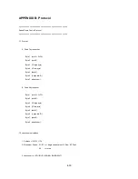
Страница 40: ...4 39 APPENDIX B Protocol 0 1 2 3 4 5 6 3 4 7 5 4 6 6 0 0 0 0 0 8 9 ...

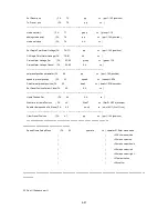
Страница 41: ...4 40 2 2 1 2 5 0 0 5 1 9 1 9 1 9 5 0 0 1 A A 5 1 A 0 0 1 5 0 0 5 B B A 5 9 0 0 0 0 ...

Страница 42: ...4 41 0 0 0 0 1 1 5 1 1 0 0 5 5 0 0 A A A 5 5 C 9 9 9 9 C 9 9 7 0 0 0 0 2 5 5 9 9 5 ...

Страница 43: ...4 42 2 2 1 2 5 0 0 3 4 4 7 9 4 7 5 5 0 0 4 D D 7 9 0 0 ...

Страница 44: ...4 43 P N MW01G00500 ...

Отзывы: