background image


Speed Dome 

EPTZ2700/EPTZ2700I 


USER MANUAL 


Date: Oct. 2008 

Содержание EPTZ2700

Страница 1: ...Speed Dome EPTZ2700 EPTZ2700I USER MANUAL Date Oct 2008...

Страница 2: ...Needed 14 2 3 Initial Setup 15 2 3 1 Address Setting 15 2 3 2 Communication Protocol Setting 19 2 3 3 Transmission Speed Setting Baud Rate Setting 19 2 4 Bracket and Speed Dome Installation 20 2 4 1...

Страница 3: ...NEGATIVE 37 3 2 9 WIDE DYNAMIC RANGE 37 3 2 10 EXIT 37 3 3 POSITIONS 38 3 4 OSD AREAS 41 3 4 1 CAM TITLE 41 3 4 2 AREAS 41 3 4 3 DIRECTIONS 43 3 4 4 DISPLAY 45 3 4 5 EXIT 46 3 5 AUTO MODES 47 3 5 1 AU...

Страница 4: ...S 56 3 6 3 EXIT 57 3 7 SYSTEM 58 3 8 INFO 59 3 9 EXIT 60 4 EPTZ2700 2700I FUNCTION SETUP AND OPERATION 61 4 1 Manual Control Mode 61 4 2 Auto Pan Mode 61 4 3 Position Setting 62 4 4 Tour Mode 63 4 5 A...

Страница 5: ...to 360 1sec No matter high speed scanning or low speed scanning the solid base can avoid vibration This full functioned speed dome can perform best quality images z EPTZ2700 for outdoor model EPTZ270...

Страница 6: ...to 16 positions Up to 256 speed domes can be supported on a RS 485 bus when all speed domes are controlled by keyboard EKB500 Built in fan to enhance heat dissipation at high temperature and circulat...

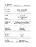
Страница 7: ...Auto 2x 4x 6x 10x 16x 32x Fix 2x 4x 6x 10x 16x 32x Shutter Selection AUTO A FLK Manual 1 50 1 10000 selectable Lens Type 27x optical zoom f 3 25 mm wide to 88 0 mm tele F1 5 to F3 8 Zoom Ratio 270x m...

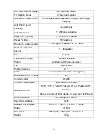
Страница 8: ...9 available Tour 16 groups Tour point per group 16 preset positions Pattern 4 patterns with 90 sec long each Fan Fan auto starts Position Accuracy 0 1 Alarm 4 in 2 out with tour position auto triggeri...

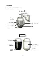
Страница 9: ...1 Profile of EPTZ2700 EPTZ2700I Wall Mount Bracket Sun shield optional Bubble Camera main body Top housing Camera module Outer housing EPTZ2700I Bubble Outer housing Top housing Camera main body Camer...

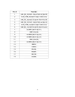
Страница 10: ...ack after finishing connecting to all cables The connectors of cable names are marked on the board in white text There are 4 alarm inputs and 2 alarm outputs available represented by Pin 1 12 Pin 13 a...

Страница 11: ...utput Normal Close B 4 ALM_NO_A Alarm Output Normal Open A 5 ALM_COM_A Alarm Output Common A 6 ALM_NC_A Alarm Output Normal Close A 7 ALMIN1 Alarm Input 1 8 GND Ground 9 ALMIN2 Alarm Input 2 10 ALMIN3...

Страница 12: ...PTZ2700 EPTZ2700I to a monitor 3 Connect the power to the EPTZ2700 EPTZ2700I and a keyboard EKB500 After the EPTZ2700 EPTZ2700I finishes the self test mode you can start to operate the EPTZ2700 EPTZ27...

Страница 13: ...camera module top housing with a base board pin connector and outer housing with bubble plus one tool packet in the package The detail accessories are listed below Standard Camera Main Body x 1 Top H...

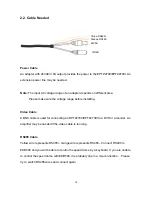
Страница 14: ...able A BNC cable is used for connecting an EPTZ2700 EPTZ2700I to a DVR or a monitor An amplifier may be needed if the video cable is too long RS485 Cable Yellow wire represents RS485 orange wire repre...

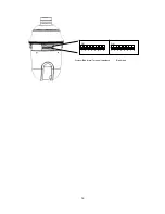
Страница 15: ...hanging 2 3 1 Address Setting The address code of the EPTZ2700 EPTZ2700I should be set to correspond properly with a control device to control multiple dome cameras The address codes are made up by th...

Страница 16: ...16 ON 1 2 3 4 5 6 7 8 ON 1 2 3 4 5 6 7 8 ID address Protocol Baud rate Terminal resistance...

Страница 17: ...s Switch Address Switch Address Switch Address Switch Address Switch Address ON 1 2 3 4 5 6 7 8 Switch Address 65 ON 1 2 3 4 5 6 7 8 66 ON 1 2 3 4 5 6 7 8 67 ON 1 2 3 4 5 6 7 8 68 ON 1 2 3 4 5 6 7 8 6...

Страница 18: ...91 Switch Address Switch Address Switch Address Switch Address Switch Address Switch Address ON 1 2 3 4 5 6 7 8 Switch Address 193 ON 1 2 3 4 5 6 7 8 194 ON 1 2 3 4 5 6 7 8 195 ON 1 2 3 4 5 6 7 8 196...

Страница 19: ...dome EPTZ2700 EPTZ2700I will enter a self test mode 2 3 3 Transmission Speed Setting Baud Rate Setting The 4th and 5th bits on the PCB board are used to set the Baud Rate The default baud rate settin...

Страница 20: ...regulations Service personnel should expect potential problems such as surface strength surface material falling objects outer breaches building vibration or other similar conditions 2 Check for all...

Страница 21: ...on location that is a wall a pole or a ceiling needs to support above five times the total weight of the camera assembly about 16 kg to avoid shaken images and dropping 1 Pull the hole of the base boa...

Страница 22: ...e of the top housing There are totally 3 desiccant packs to be applied 3 When all the desiccant packs are pasted and alarm cables are connected properly put the base board back to its original place y...

Страница 23: ...and video cable you tread from the wall or ceiling RS485 cable has to be connected via a terminal block If you need to connect alarm cable thread the alarm cable through the second hole 5 Screw in 4 s...

Страница 24: ...24 6 Thread the cable through the bracket 7 Screw the top housing to bracket by using a hexagon wrench...

Страница 25: ...e of base board to open it again Connect the power and RS485 wires back to power pin and RS485 pin If you need to connect alarm connect alarm cable to alarm pin 10 There is a rope pendant from the top...

Страница 26: ...26 a Locate the hook first b Clasp the rope to the hook firmly Hook...

Страница 27: ...27 c Done...

Страница 28: ...ain body toward the bracket until it is firmly fixed to the bracket To release it press orange buttons at both sides of the body 12 Twist the cover of main body to top housing clockwise until it is fi...

Страница 29: ...era module on the mechanical part is very sensitive Please be careful when installing this part 13 Turn on the power and start to operate the EPTZ2700 Note When turning on the power EPTZ2700 will ente...

Страница 30: ...ng pendant mount adapter is used for installing a speed dome on the ceiling indoors or outdoors The extension poles are available for the pole mount 2 5 2 EPTZ PMA Pole Mount Adapter The pole adapter...

Страница 31: ...31 2 5 3 EPTZ CMA Corner Mount Adapter The corner mount are used for installing a wall mount bracket to a 270 corner of walls indoors or outdoors...

Страница 32: ...Structure of the Setup Menu Press MENU to enter camera setup menu Turn the Joystick up down to change subentries and right left to change the setting If there is an arrow at the end of selection it me...

Страница 33: ...ck Left Right to enter Exposure sub menu VIDEO SETTINGS POSITIONS OSD AREAS AUTO MODES ALARM SYSTEM INFO EXIT EL SHUTTER AUTO SLOW SHUTTER OFF IRIS MODE AUTO AE SPEED 0I 6 EXIT EXPOSURE FOCUS MODE ONE...

Страница 34: ...or NTSC and PAL 1 10000 1 10000 sec shutter for both NTSC and PAL SLOW SHUTTER Slow electronic shutter In order to enhance the view in the low lux environment slow shutter allows more light go through...

Страница 35: ...t trigger command is received This function prevents the wrong focus in dark AUTO Auto focus is enabled It automatically adjusts the focus position to maximize the high frequency content of the pictur...

Страница 36: ...earer ON Enable Back Light Compensation OFF Disable Back Light Compensation 3 2 6 DAY NIGHT In Day Night we define the ICR IR Cut Removable mode settings The camera is built in an infrared IR Cut Filt...

Страница 37: ...shooting a very bright subject ON WDR function is fixed to ON OFF WDR function is fixed to OFF AUTO WDR function is changed to ON or OFF automatically according to backlight condition of the object WD...

Страница 38: ...Left Right to select preset position There are totally 36 preset positions can be set Once the preset position is selected go to RETURN and turn the joystick Left Right to exit from current page diag...

Страница 39: ...nu Clear Select Clear and press Enter key of keyboard and the POSITION will be cleared You will automatically go back to the sub menu of PRESET POSITION see diagram 3 7 diagram 3 7 PRESET NO 1 POSITIO...

Страница 40: ...lect the white balance for the preset position from Auto Indoor and outdoor TITLE Enter title name for the preset position Turn the joystick Up or Down to select the character Turn the joystick Left o...

Страница 41: ...or Right to select the character position Once the title is inputted turn the joystick to the last character and keep turning right again to return to previous mode 3 4 2 AREAS Press Enter key of keyb...

Страница 42: ...Range section and press Enter key to enter Range sub menu Use the joystick to move speed dome to its left position Press IRIS key to save left position setting and go to next step or press IRIS to ca...

Страница 43: ...S sub menu see diagram 3 12 diagram 3 12 Press Enter key of keyboard or turn joystick Left Right to enter DIRECTIONS sub menu see diagram 3 13 diagram 3 13 1 Press Enter key of keyboard or turn joysti...

Страница 44: ...return diagram 3 14 4 Go to DEFAULT NORTH and press Enter key to set the north position as default north position 5 Go to Return and turn joystick Left Right to return to previous menu DIRECTIONS NOR...

Страница 45: ...d Camera Status OFF do not show OSD 2 SEC show OSD for 2 seconds 5 SEC show OSD for 5 seconds 10 SEC show OSD for 10 seconds 2 CAMERA TITLE YES show camera title NO do not show camera title 3 DIRECTIO...

Страница 46: ...tiple when zoom in or zoom out NO do not show zoom multiple 7 FAN YES show fan indication when fan is enabled NO do not show fan indication 8 CAMERA STATUS YES shows camera status NO do not show camer...

Страница 47: ...ENDLESS MODE ON enable endless mode The speed dome will perform 360 degree endless VIDEO SETTINGS POSITIONS OSD AREAS AUTO MODES ALARM SYSTEM INFO EXIT AUTOPAN PRESET TOURS PATTERN AUTO RESUME OFF RES...

Страница 48: ...ect dwell time of the right position from 1 99 seconds e SET LEFT POS Press Enter key or turn the joystick Left Right to enter SET LEFT POS menu Turn the joystick to the position where you wish to set...

Страница 49: ...19 g DEFAULT ON all settings in AUTOPAN menu will be returned to default values OFF the setting in AUTOPAN menu is not default value h RETURN Turn joystick Left Right to return to previous menu 3 5 2...

Страница 50: ...r Down to select tour speed from 1 255 or default Press Enter key when you finish Tour setting of preset position e PREV PAGE NEXT PAGE Turn the joystick Left to go previous page or turn joystick Righ...

Страница 51: ...to set Press IRIS when you finish setting pattern tour Press IRIS if you wish to cancel this action At duration column of PATTERN SETUP menu you will see the duration time of pattern you set PATTERN...

Страница 52: ...s mode if no action for a period Turn the joystick Left Right to set AUTO RESUME Auto Resume is selectable from OFF After 30S After 1M after 5M After 10M After 30M and After 60M After this period of t...

Страница 53: ...Flip 3 5 8 EXIT Exit from the current menu 3 6 ALARM In main menu turn joystick Up or Down to select ALARM Turn joystick Left or Right to enter ALARM sub menu see diagram 3 24 diagram 3 24 3 6 1 ALARM...

Страница 54: ...FF Disable alarm input diagram 3 25 c REACTION The action will be taken when alarm is triggered OFF No reaction will be taken when alarm is triggered POSITION When the alarm is triggered speed dome wi...

Страница 55: ...selection d DURATION Duration of alarm input TIMEOUT Turn the joystick Left or Right to select on TIMEOUT and press Enter key to select time out Time out is selectable from 1 99 Press Enter key again...

Страница 56: ...he alarm output selected Select NO to disable Alarm input 3 e INPUT4 Select YES to enable Alarm input 4 for the alarm output selected Select NO to disable Alarm input 4 f MOTION Select YES to have ala...

Страница 57: ...57 Select NO to disable this function i RETURN RETURN to the previous menu 3 6 3 EXIT Exit from the current menu...

Страница 58: ...you have done b LANGUAGE Select language The current version only supports English version c PASSWORD Press Enter key or turn joystick Left Right to enter password sub menu diagram 3 28 VIDEO SETTINGS...

Страница 59: ...t to return to previous menu without saving changes f LOAD DEFAULT Press Enter key to load default values all values will return to g EXIT Exit from current menu 3 8 INFO In main menu turn joystick Up...

Страница 60: ...the speed dome runs to preset position f X CONT X axis counter This counter counts the x axis movement and 1 is counted when the speed dome pans 360 g Y CONT Y axis counter This counter counts the y a...

Страница 61: ...ng Set Home If you set the time to 0 minute then the camera will go back to home if there is no keyboard operation in 5 seconds This is the minimum no action time for HOME mode Note If HOME function i...

Страница 62: ...e are up to 192 positions can be preset Three specific preset positions can be set as follows 92 Set Left Limit Stop A position 93 Set Right Limit Stop B position 95 Enter Menu mode Use keyboard contr...

Страница 63: ...eset position You can set the going to speed 1 239 dwell time 1 239 seconds and the title of the position Shift the joystick Right Left to change bits and shift the Joystick Up Down to change the alph...

Страница 64: ...ns 1 2 and 3 The camera runs 1 2 3 1 2 3 in the One way tour mode and 1 2 3 2 1 in the To and fro tour mode Note 2 You could set a pattern tour Press Set Tour and input 0 press Enter Sway the joystick...

Страница 65: ...After powering on the speed dome it will detect alarm status automatically 4 6 Other Operations The EPTZ2700 EPTZ2700I can work with a DVR that has PTZ control functions and a matching protocol The av...

Страница 66: ...297 0081 www everfocus com Your EverFocus product is designed and manufactured with high quality materials and components which can be recycled and reused This symbol means that electrical and electro...

Отзывы: