background image

III. 

Lens Available

IV. 

Installation Instructions

1.

Remove the plastic dome cover.

2.

Loosen the two screws of the supporting bracket to 
remove the camera body. 

3.

Using four screws to fix the camera base on the ceiling.

4.

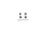
Put the camera body back to the supporting bracket, the 
connector of the back panel should always be placed to 
camera’s left lower corner, in order to obtain the image of 
best quality. Tighten the 2 screws to fix the camera. Please 
refer to the back panel diagram shows as below:             

* Standard board lens f=3.6 mm, F=2.0 mm.

* Other available lens :  -2     Lens f=2.5 mm, F=2.0 mm

-4     Lens f=4.3 mm, F=2.0 mm

-6     Lens f=6.0 mm, F=2.0 mm

-8     Lens f=8.0 mm, F=2.0 mm

-3P   Pinhole lens f=3.7 mm, F=3.0 mm

6

Содержание ED200 Series

Страница 1: ...ED200 INSTRUCTION MANUAL...

Страница 2: ...use liquid cleaners or aerosol cleaners use a damp cloth for cleaning Do not use attachments not recommended by the appliance manufacturer as they may cause hazards Do not use this appliance near wat...

Страница 3: ...sult in fire or electric shock Do not place this appliance on an unstable cart stand or table The appliance may fall causing serious injury to a child or adult and serious damage to the appliance Use...

Страница 4: ...th an arrowhead symbol within an equilateral triangle is intended to alert the user to the presence of non insulated dangerous voltage within the product s enclosure that may be of sufficient magnitud...

Страница 5: ...lation If this equipment does cause harmful interference to radio or television reception which can be determined by turning the equipment off and on the user is encouraged to try to correct the inter...

Страница 6: ...with DSP The sensor is featured with Auto Electronic Shutter Automatic Gain Control and Auto White Balance function II Precautions Do not expose the camera to humidity and dust Outdoor application wi...

Страница 7: ...the supporting bracket the connector of the back panel should always be placed to camera s left lower corner in order to obtain the image of best quality Tighten the 2 screws to fix the camera Please...

Страница 8: ...of the camera to a color monitor or other video device through a 75 ohm type coaxial cable with BNC female connector at cable extension a Floor Mount b Ceiling Mount c Wall mount aim to the right d W...

Страница 9: ...outer plug 7 Once the image appears on the monitor loosen the fixing screw located at the lens mount then adjust the focus and diaphragm of the lens to obtain the best picture When the ideal picture i...

Страница 10: ...380 TV Lines Sensitivity 0 3 Lux F 1 2 S N ratio Over 48 dB Electronic shutter Up to 1 100 000 Auto white balance Yes Gamma correction 0 45 Video output 1 0Vp p 75 ohm Power source 12V DC 10 Sync Mod...

Страница 11: ...ED200 Camera unit User s manual VI Package Contents 10...

Страница 12: ...signed and manufactured with high quality materials and components which can be recycled and reused This symbol means that electrical and electronic equipment at their end of life should be disposed o...

Отзывы: