background image

Section

2: Getting

Started

This

chapter contains

a

brief description

on how

to

install

the Magic

I/O.

If multifunction cards are

new

to

you, we

suggest using

the

more

comprehensive instructions

in

Section

4.

Installation.

Physical Layout

DTE/DCE FOR

OPTIONAL

SERIAL PORT

2

SERIAL PORT

\

FORCE TRUE

FOR OPTIONAL

EYE]

SERIAL PORT

[eee

|

FORCE TRUE FOR

1400

EL

SERIAL PORT

1

U2 16450

[

or 8250

Apa

pe

|

|

STANDARD

SERIAL PORT

Ly

f~__

DTE/DCE FOR

SERIAL PORT

1

~~

Cae

SW1

I~

PARALLEL PORT

[>

PTRINT

C

CLKEN

~

SERCHINT

LPTSEL

CS

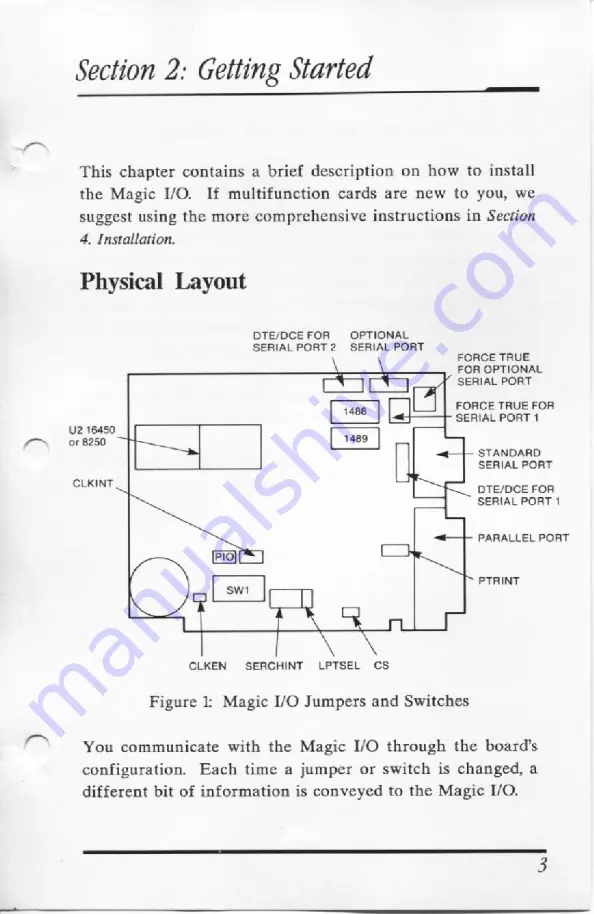
Figure

1:

Magic I/O

Jumpers

and Switches

You

communicate

with

the

Magic I/O

through the

board's

configuration. Each

time

a

jumper or switch

is

changed,

a

different bit of information

is

conveyed to

the

Magic I/O.

Содержание Magic I/O EV-170

Страница 1: ...A EVEREX Magic 1 0 Input Output Adapterfor the IBM PC XT AT RAT mdIO GUIDE EVER for EXcellence MAN 00054 40 ...

Страница 2: ......

Страница 3: ...Magic 1 0 Input Output Adapterfor the IBM PC XT AT OWNER S MANUAL AND REFERENCE GUIDE EV 170 and EV 170A VERSION 4 0 EVEREX SYSTEMS INC 48431 MILMONT DRIVE FREMONT CA 94538 ...

Страница 4: ...rporation DISCLAIMER While we do our best to avoid such a situation Everex Systems will not be responsible for any loss of information resulting from the use of the product This manual is copyrighted All rights are reserved This document may not in whole or part be copied photocopied reproduced translated or reduced to any electronic medium or machine readable form without prior consent in writing...

Страница 5: ...ed by turning the equipment off and on the user is encouraged to try to correct the interference by one or more of the following measures 1 Reorient the receiving antenna 2 Reorient the computer with respect to the receiver 3 Move the computer away from the receiver 4 Plug the computer into a different outlet so that computer and receiver are on different branch circuits 5 Ensure that card mountin...

Страница 6: ...Notes iv ...

Страница 7: ...C I O 6 Setting the Switches and Jumpers 6 Using the Software to Configure the Magic I O 9 Configuring Without the SOftWare mmm 11 Th Serial Ports 1 The Parallel Port 18 The Real Time Clock 22 SECTION 4 INSTALLATION 24 Physical Installation 24 Testing the Magic I O 28 APPENDIX I THE EVERCLOCK SOFTWARE 29 APPENDIX II PC WRITE 31 APPENDIX III HANDSHAKING SCHEMATIC 2 ...

Страница 8: ...c I O will work in more systems with more combinations of hardware and software than any other I O card on the market To complement its many features the Magic I O comes with a menu driven diagnostics set up utility program EVI170 which will guide you through the configuration of your board and will test the board once it is installed This manual will provide you with all of the information that y...

Страница 9: ...L SERIAL PORT 2 SERIAL PORT FORCE TRUE FOR OPTIONAL EYE SERIAL PORT eee FORCE TRUE FOR 1400 ELSERIAL PORT 1 U2 16450 or 8250 Apa pe STANDARD SERIAL PORT Ly f __ DTE DCE FOR SERIAL PORT 1 Cae SW1 I PARALLEL PORT PTRINT C CLKEN SERCHINT LPTSEL CS Figure 1 Magic I O Jumpers and Switches You communicate with the Magic I O through the board s configuration Each time a jumper or switch is changed a diff...

Страница 10: ...rt is enabled its default setting is COM 2 at IRQ 3 and it is set as a DTE device with no force trues If you do not want to change any of these settings you can proceed to install the board If you do want to change a setting you can use either the Installation Set Up option from the main menu of the EV170 utility software or the instructions in this manual we suggest using the Installation Set Up ...

Страница 11: ...ter We highly recommend using the software Install the board into your system and boot up your computer with DOS Test the Magic I O with the software utility programs that accompany the Magic I O To access these programs insert the Magic I O utility diskette into the floppy drive and type EV170 Enter First choose the Installation Set Up option and inform the software of the Magic I Os configuratio...

Страница 12: ... the board Setting the Switches and Jumpers The Magic I O comes from the factory with the parallel port enabled in the printer mode with port addresses from 378 to 37F and the interrupt at IRQ7 The 9 pin serial port is enabled and set as COM1 at IRQ4 and as a DTE device with no force trues The optional 10 pin serial port 2 is set as COM2 at IRQ3 and as a DTE device with no force trues You communic...

Страница 13: ... yo ELSERIAL PORT 1 U2 16450 or8250 TH 1489 B STANDARD SERIAL PORT CLKINT B DTE DCE FOR SERIAL PORT 1 PARALLEL PORT PTRINT CLKEN SERCHINT LPTSEL CS Figure 22 The Magic I O If you have not already done so remove the Magic I O from its box Locate all of the key areas which are pointed outin this figure ...

Страница 14: ... Installation Set Up program is included on the Magic I O Utility diskette which will simplify the configuration procedures For those of you who choose not to use this program information is provided in this manual We strongly advise using the software program Please read on to see what you need to consider when setting up your board To access the software type EV170 and the ENTER key If you will ...

Страница 15: ...rive A 2 At the A prompt type EV170 ENTER Note To choose an option use the arrow keys to move the highlighted area to the option you desire then hit the Enter key to activate your choice The utility main menu will appear on the screen Since you are concerned with installing your Magic I O choose the Installation Set Up option 3 To make configuring the board easy have the board in front of you as y...

Страница 16: ...tions the screen will display a picture of the Magic 1 0 and will show you what you need to set Physically set the switches jumpers on your board to correspond with those set on the screen The picture on the screen points out the correct jumper settings that will communicate the configurations you indicated to the Magic 1 0 You can now skip the next section 10 ...

Страница 17: ...W1 on the Magic I O selects the COM ports for the serial ports The factory default setting is COM 1 for Serial Port 1 and COM 2 for Serial Port 2 Both serial ports share the 8 position SW1 dipswitch Use the following tables s if you wish to change the default configuration of the serial port s TABLE 1A Com Port Switch Settings For Serial Port 1 SW1 POSITION 3 w COO CoOcs oO OO CE oe COO oo OOo oOo...

Страница 18: ...Default Setting Jon push switch up Jorr puswswircn cown The I O port addresses of the COM Ports are fixed Table 1C lists the I O Port Addresses of COM Ports 1 through 4 COM Port I O Port Addresses TABLE 1C COM PORT UO PORT ADDRESSES 1 3F8 3FF 2 2F8 2FF 3 3E8 3EF 4 2E8 2EF Do NOT assign two serial ports to the same COM port 12 ...

Страница 19: ...M1 Interrupt 5 fixed drive Interrupt 6 floppy drive Interrupt 7 printer Each serial port in your system also requires an interrupt level The serial port interrupts are selected by the jumpers at location SERCHINT Serial Channel Interrupt Generally COM Port 1 uses interrupt 4 while COM Port 2 uses interrupt 3 Many software programs support COM Ports 3 and 4 which share the same interrupt levels as ...

Страница 20: ...ct your serial port interrupt TABLE 2 Interrupt Jumper Settings For the Serial Port SERCHINT SERIAL PORT 1 SERIAL PORT 2 IRQ2 mice me Nel m IRQ3 i IRQ4 m m a u IRQS ou Default Setting Note To disable the IRQ do not use any jumpers 14 ...

Страница 21: ...ermined and will vary depending on whether the device is DTE or DCE The exchanging of control signals between the DTE device and the DCE device is called handshaking For the serial ports there are two blocks of DCE DTE jumpers on the Magic I O labeled SCHI for Serial Port 1 and SCH2 for Serial Port 2 In the factory default DTE setting all six shunts are connecting both rows of pins To set the seri...

Страница 22: ...y If you cannot determine whether your serial device is DCE or DTE and the serial device is not working with the default DTE setting try changing the setting to DCE Force trues Most of the devices that you can attach to a serial port will do their part in the handshaking process and will send the required control signals However certain devices do not provide some or all of the required functions ...

Страница 23: ...r Serial Port 2 For each three pin row the shunt connecting the left and center pins disables force trues while moving the shunt to the right and center pins enables force trues Refer to the following figure DSR OO EC cts 0 0lQ DCD 90 Oia RI DONO Figure 5 Setting No Force Trues If you need to enable any force true signals be careful to use the jumpers that correspond to the correct serial port For...

Страница 24: ... to the following figure Printer Mode General Purpose 1 0 Figure 6 Configuring the Parallel Port PIO The Parallel Port in Printer Mode When you turn your computer on it searches for the number of printer ports installed in your computer The computer can recognize up to three printer ports The computer follows a priority for these ports and refers to them as LPT1 LPT2 and LPT3 The I O port address ...

Страница 25: ...most monochrome display adapters the Magic I O printer port is configured as LPT2 with the port address 378 37F It is possible to change the I O port address of the Magic I O to LPT1 or LPT3 if the address 378 37F conflicts with another parallel device in your computer If you have a graphics adapter with a parallel port configured with a port address starting at 3BC confirm that the port address o...

Страница 26: ...Settings LPTSEL PORT LPTSEL LPT ADDRESS SETTING LPT 2 3783TF OO a I LPT 3 278 27F a T ws LPT 1 3BC 3BF aa EI8 DISABLED N A e a O Default Setting NOTE Every parallel port in your computer must have its own I O port address In our references to the parallel port designation we refer to the parallel port at I O address 3BC as LPT the port address at 378 as LPT2 and the port address at 278 as LPT3 20 ...

Страница 27: ...sent to 3BE 37A 2BE or 27A depending upon the port address you have chosen for the parallel port Before a write to the parallel port you should enable the output buffer by setting bit 5 of the control register to 0 Before a read from the parallel port you should disable the output buffer by setting bit 5 of the control register to 1 You should refer to more detailed documents on the printer port i...

Страница 28: ...s are in this category you can disable the Magic I O s clock calendar by removing the black plastic shunt from the CLKEN jumper If you do remove the shunt putit back over one pin for safekeeping The clock calendar interrupt can be enabled by setting the CLKINT ClocK Interrupt jumper The default clock calendar interrupt setting is the disable position Table 5 gives you the possible interrupt levels...

Страница 29: ...grade Kit to change the I O port address to 340 35F If you do change the address to 340 35F use the software on the Everex Systems utility diskette called SCLOCKLEXE and EVECLOCKLEXE use these two programs instead of the software called SCLOCK and EVECLOCK The following figure points out the location of the IC chip that you need to replace to enable 1 0 address 340 35F SW1 a Figure 7 Replacing the...

Страница 30: ... following adjustments before continuing a When you order an optional serial port you receive a special ribbon cable with a ten pin female connector at one end and a 25 pin male connector at the other end The optional serial port is the 10 pin connector at J3 in the upper right corner of the Magic 1 0 Connect the ten pin end of the cable to J3 as shown in the following figure J3 OPTIONAL SERIAL PO...

Страница 31: ...with a notch or a dot refer to the figure below If you look carefully at the Magic I O board each chip socket has the outline of a notched chip in the proper orientation Be sure to insert the chip following this orientation To install the chips insert the tips of the pins into the holes in the socket Make sure the alignment is exactly right then press the chip into place Figure 9 Installing an IC ...

Страница 32: ...screw which holds the metal cover in place You should save the screw as you can use it to secure the Magic I O into place Figure 10 Removing The Slot Cover NOTE If you are going to install the Magic I O into short slot 8 of the IBM XT you must place a jumper plug over both pins of the System Select jumper CS Gently but firmly insert the Magic I O card all the way into the expansion slot Make sure ...

Страница 33: ...ce into the appropriate port connector Replace the cover to your system and any cords or cables you disconnected earlier Boot up your system from DOS Test the Magic I O with the software programs on the utility diskette Type EV170 and press the enter key First choose the Installation Set Up option and inform the software about how your board is configured Then return to the main menu and choose th...

Страница 34: ...the A prompt EV170 ENTER The Magic I O s main menu will appear on the screen Choose the Installation Set Up option and go through the utility to inform the program how the Magic I O is configured After you have told the program how the Magic I O is setup return to the main menu and choose the TestChip Functions option Go through each Chip Test The chips will be tested sequentially The chips under ...

Страница 35: ...3 30 pm equals 15 30 in 24 hour time NOTE For Users With the Clock Calendar Upgrade Kit If you changed the port address of the clock calendar to 340 35F use the software called SCLOCK1 and EVECLOCK1 instead of the software mentioned in this appendix 2 Insert the Magic I O utility diskette in drive A At the A prompt type SCLOCK ENTER This program stores the correct time and date from your system DO...

Страница 36: ...up Therefore by placing the EVECLOCK COM program in your AUTOEXECBAT file this is accomplished for you automatically If you already have an AUTOEXECBAT file present on your system disk add the line eveclock to this file If you do not already have such a file create one in your root directory that contains the following lines COPY CON AUTOEXEC BAT ENTER EVECLOCK ENTER Press the F6 function key and ...

Страница 37: ...dix II PC Write Included with your Magic I O is a word processing program called PC Write The manual for PC WRITE is on your utility diskette If you wish to use this utility you should type TYPE READ ME Sit ...

Страница 38: ... Handshaking Schematic The following portion of the Magic I O s schematic diagram details the handshaking functions performed by the DTE DCE and force true jumpers DB 9 CONNECTOR DS1488 56 Ai csout NC our INTRPT 32 ...

Страница 39: ...Notes 33 ...

Страница 40: ... EVEREX SYSTEMS INC 48431 MILMONT DRIVE FREMONT CA 94538 SALES 415 683 2100 ERS TECH SUPPORT 415 498 1115 FAX 415 651 0728 TELEX 5101000590 MAN 00054 40 id ...

Отзывы: