background image

EVER POWERLINE RT PLUS 6000 / 10000 UPS Operating Manual 

21 

www.ever.eu


Pomoc Techniczna, tel.: +48 61 6500 400


2020-03-20 13:06


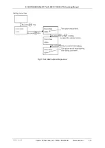
the alarm and will go back to the bypass mode. Before manually running the UPS 

unit, check and remove the cause of the failure. 

4. 

Event log reset

: removing all saved failures and errors, which occurred during the 

operation of the UPS unit, from its memory.  The device can save a maximum of 

100 events. 

5. 

Restoring Factory Settings

: after activating this option all settings will be reset to 

the default factory settings.  This operation can be carried out only in  the bypass 

mode. 


Fig 10: Control menu 

Содержание POWERLINE RT PLUS 10000

Страница 1: ......

Страница 2: ... THE UPS WITH A BATTERY MODULE RACK VERSION 34 DISCONNECTING THE BATTERY MODULE 35 INSTALLATION OF THE PDU optional equipment TOWER VERSION 36 INSTALLATION OF THE PDU optional equipment RACK VERSION 39 Starting up the UPS unit power supply from the mains 40 Starting the UPS up from the battery cold start 41 Switching off the UPS 41 Switching from MAINS mode to BYPASS mode service bypass by means o...

Страница 3: ... the purchased UPS unit will meet your expectations This manual contains all relevant information to ensure correct and safe operation of the unit Please read this manual carefully and thoroughly prior to using the EVER POWERLINE RT PLUS unit This will help you operate the unit correctly and safely The POWERLINE RT PLUS units were designed for computer servers small computer networks workstations ...

Страница 4: ... is done via software Availability of the ECO mode further improves the efficiency of the power supply system through the ability to differentiate between periods with varying degrees of safeguards HID USB communication interface the UPS can operate with other devices without the necessity to install software Scalability extension of autonomous operation time thanks to the ability of connecting up...

Страница 5: ...s should be conducted only by qualified service technicians properly authorized pursuant to the valid legal regulations CAUTION The unit should be operated and stored in conditions complying with the requirements set in the specification technical documentation CAUTION The device is completely disconnected from the mains only when the power lead is removed from the mains socket the plug is removed...

Страница 6: ... circuit the resulting high current may cause serious burns or scalds CAUTION There are no user serviceable parts inside the UPS unit CAUTION The POWERLINE RT PLUS UPS units are not intended to work directly with medical equipment life supporting equipment or any other equipment that may have effect on health B Installation information and requirements CAUTION The POWERLINE RT PLUS UPS units may o...

Страница 7: ... warm environment moisture condensation may appear The UPS unit must be completely dry before installation and operation The acclimatization time should be at least 2 hours UPS units and battery packs must not be installed in humid environment UPS units and battery packs must not be installed in places where they would be exposed to direct sunlight They must not be installed near sources of heat V...

Страница 8: ...o allow disconnecting in emergency the UPS unit from the connected loads regardless of the mode in which the UPS is operating To minimize the risk of fire connections should only be made to circuits electrical systems whose rating is adequate for the connected loads with properly selected overcurrent protection Additionally the breaker should feature at least a 3 mm insulating air gap C Operation ...

Страница 9: ...who have legally required protection gear may replace batteries CAUTION Risk of electric shock Dangerous voltage may be present between the battery circuit and the grounding point Batteries have high short circuit current and pose a risk of electric shock The following precautions should be taken when working with batteries remove jewelry watches rings and other metal items only use tools with ins...

Страница 10: ...ate protection against shocks vibrations and impact The unit should be operated and stored in conditions meeting the requirements in the product specification UPS units must be stored in a dry room with suitable ventilation If a UPS is to be stored over a longer period of time its batteries must be recharged at least every 6 months The recharging procedure must always be recorded and documented Al...

Страница 11: ...e made with photos of the damage Keep the packaging for future transport operations CAUTION Water vapor may condensate on the UPS unit s elements if packaging is removed from the device in low temperatures Do not install the UPS until its interior and housing are completely dry electric shock risk What s in the box Check carefully the contents of the packaging The packaging should contain the UPS ...

Страница 12: ...000 10000 units Fig 1 View of the rear panel of POWERLINE RT PLUS 6000 10 000 1 Intelligent card slot SNMP card dry contact 2 USB communication port 3 Dry contact 1 dry IN 1 dry OUT 4 RS232 communication port 5 EPO connector 6 RJ11 connect to PDU 7 Parallel card optional 8 Output circuit fuse sockets IEC 320 C13 10 A 9 Output sockets IEC 320 C13 10 A 10 Input Output terminal 4pole IPL IPN OPL OPN ...

Страница 13: ...y module for POWERLINE RT PLUS 6000 10000 units Fig 2 View of the rear panel of the battery module for POWERLINE RT PLUS 6000 10 000 1 Fuse board cover 2 EBM plug 3 EBM connector PDU optional equipment An external PDU panel can be connected to UPS which is equipped with a manual BYPASS switch and additional IEC 320 C13 and IEC 320 C16 sockets The PDU elements are shown in Figs 3 4 Fig 3 View of th...

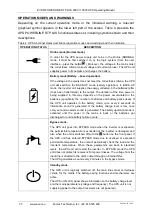
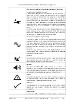
Страница 14: ...PL OPN PE is screw 8 RJ11 connect to UPS only for RT UPS HOW IT WORKS The user interface is the control panel Fig 5 in which there are LCD display with LEDs indicating the status of the power supply and function keys Table 1 presents the description of the buttons of the control panel The significance of individual LED indicators and the ways in which each mode of operation is signalled is shown i...

Страница 15: ...n the unit is in fault mode press this button for 1s to stop alarm and clear fault Scroll up Press this button for 100ms 1s to scroll up the menu option Scroll down Press this button for 100ms 1s to scroll down the menu option Enter next menu tree Press this button for 100ms 1s to select the present menu option or enter next menu but do not change any setting Select one menu option Press this butt...

Страница 16: ...cularly NORMAL BATTERY BYPASS FAULT NORMAL Flashing Depended on the fault warning status or other status LED Lightened constantly or flashing Table 3 Sound signals for specific states of the UPS unit Event Acoustic signal Fault active Continous Over Load Warning active 2 Beep every second Other Warning active Beep every second Battery Mode Beep every 4 seconds if battery low buzzer Beep every seco...

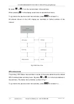
Страница 17: ...o the previous main menu window press for at least 1 s All screens shown on the LCD display are described in further sections of the manual Fig 6 Main menu tree UPS status menu The primary UPS Status menu window consists of the same elements as the default UPS functional state summary menu By press or 1s to the next windows in the submenu The status menu structure is show in Fig 7 To go back to th...

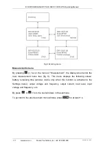
Страница 18: ...xt event menu tree All the previous events alarm and fault have been recorded here The information includes the illustration the event code and the precise time of UPS when the event happened fig 8 By press or 1s all the events could be displayed one by one The max number of record is 100 when the number is larger than 100 the latest will replace the previous To go back to the previous main menu w...

Страница 19: ...nt the display would enter the next measurement menu tree fig 9 This menu displays the following values battery remaining time window visible only when this function is activated in the Settings menu output voltage and frequency output current load level input voltage and frequency etc By press or 1s to the next windows in the submenu To go back to the previous main menu window press for at least ...

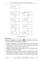
Страница 20: ...and to perform a quick 10 second battery test Before testing check that the UPS is in network mode without active alarms and that the load connected to the UPS is higher than 10 2 Shutdown of a UPS operating in parallel system The menu is visible only when parallel power supplies are connected 3 Failure status reset in case of a failure the UPS unit enters the failure mode and a sound alarm is gen...

Страница 21: ... check and remove the cause of the failure 4 Event log reset removing all saved failures and errors which occurred during the operation of the UPS unit from its memory The device can save a maximum of 100 events 5 Restoring Factory Settings after activating this option all settings will be reset to the default factory settings This operation can be carried out only in the bypass mode Fig 10 Contro...

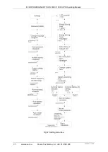
Страница 22: ... Settings menu window press 1s in the Settings menu fig 12 Remember that changing some settings cause changes in specification while others activate or deactivate some functions of the UPS unit Choosing improper settings may cause the loss of the protection functionality Settings menu block diagram including available settings options is shown in fig 12 Most of settings could only be done while UP...

Страница 23: ...EVER POWERLINE RT PLUS 6000 10000 UPS Operating Manual 23 www ever eu Pomoc Techniczna tel 48 61 6500 400 2020 03 20 13 06 Fig 12 Setting menu tree ...

Страница 24: ...EVER POWERLINE RT PLUS 6000 10000 UPS Operating Manual 2020 03 20 13 06 Pomoc Techniczna tel 48 61 6500 400 www ever eu 24 Fig 13 Set rated output voltage value ...

Страница 25: ... in the batteries specifically the number of batteries and battery packs used If the UPS unit operates in the battery mode once every 4 seconds an information sound is generated If the battery charge level is low once every second an alarm sound is generated The battery operation mode is activated until the power in the mains is back or the batteries get discharged or until a battery failure occur...

Страница 26: ...put frequency of 50 Hz or 60 Hz In case of an interruption in the mains or if the power parameters of the mains exceed permissible range the UPS unit goes into the battery mode and the device is continuously powered until battery discharge or a restoration of proper power from the mains The function may be activated via the LCD display Settings menu Power strategy or by software PowerSoft In the c...

Страница 27: ...ps back to the level of 70 Pmax After reducing the load the UPS unit returns to the network operation mode If the overload condition happens three times in a row the UPS unit will enter and remain in the BYPASS mode After reducing the load to make the UPS unit return to the online mode it is necessary to restart the unit press and hold the button for more than 1s In the battery operation mode duri...

Страница 28: ...RGENCY mode failure If the UPS unit was in online mode the output voltage will only be switched on again after the user s intervention consisting in setting the trigger to the inactive position resetting the alarm in the CONTROL menu Clear faults Reset fault status yes press any button The UPS will stop generating an alarm signal and return to BYPASS mode Then turn on the UPS press and hold the bu...

Страница 29: ... guidelines that are applicable to the UPS unit The guidelines are included in a separate document supplied with the product UNPACKING THE PRODUCT The UPS unit must be properly examined upon delivery or handover Although ever care has been taken to ensure proper and safe packaging the product may have suffered damage due to incorrect conditions in transit Should any product damage be discovered th...

Страница 30: ...nting openings must be uncovered and free of obstruction at all times Minimum distance between the UPS unit and other objects should not be less than 10 cm Connecting elements Fig 14 Connecting elements IN input connections L input phase line N input neutral line protective earthing point OUT output connections L output phase line N output neutral line protective earthing point Connection is done ...

Страница 31: ...ters of the building s electric wiring system protection should be selected to meet the requirements of the load connected to the wiring system and the type the load In extreme cases different characteristics of the building s and the UPS unit s electrical protection systems may result in the former system being activated earlier CAUTION The user is under obligation to place the following warnings...

Страница 32: ...S WITH A BATTERY MODULE The UPS unit doesn t have internal batteries It is recommended to connect 1 battery module Maximum number of battery modules 6 pcs To install the UPS with a battery module as a free standing unit follow these steps 1 Assemble the feet kit supplied with the battery module and UPS fig 16 Fig 16 Assembling the feet kit 2 Take the UPS EBM into Stabilizer bracket individually fi...

Страница 33: ...nal to the UPS 4 Remove the cover of terminal block fig 19 Fig 19 Remowe the cover 5 Connect the AC cable to terminal blocks refer to the indication on rear panel fig 14 Always use the wire gauges as specified in the installation instructions CAUTION Always connect the earthing conductor first 6 Install back the cover of terminal block CAUTION After switching the UPS on use its menu to configure t...

Страница 34: ...e should be installed directly under the UPS unit The worth of free space should be left in the cabinet for the UPS 2U worth of space for the battery module 3U To install the UPS follow these steps 1 Assemble a set of installation rails depending on the depth of the cabinet Fig 20 Fig 20 Assembling the rails Rack Kit 2 Attach the installation rails to the interior of the cabinet with bolts Fig 21 ...

Страница 35: ...fig 19 8 Connect the AC cable to terminal blocks refer to the indication on rear panel fig 14 Always use the wire gauges as specified in the installation instructions CAUTION Always connect the earthing conductor first 9 Install back the cover of terminal block CAUTION After switching the UPS on use its menu to configure the number of connected battery modules 1 6 DISCONNECTING THE BATTERY MODULE ...

Страница 36: ... the UPS system will turn to bypass mode Switch off the input breaker A few seconds later the UPS system will shut down 2 Disconnect the battery module form UPS 3 Remove the cover of terminal blocks in UPS fig 19 4 Disconnect input and output cable from UPS 5 Remove the cover of terminal blocks in PDU fig 25 Fig 25 Remove the cover 6 Connect the L N and protective ground wires to the connection te...

Страница 37: ...de of the UPS fig 28 Fig 28 Installation PDU 9 Connect the PDU cables to the connection terminals located on the back panel of the UPS Fig 14 Connect the L and N wires of the UPS IN socket PDU respectively to L and N in the IN sockets UPS and the L and N wires of the UPS OUT socket PDU connect respectively to the L and N OUT sockets UPS fig 29 Make the protective earth connections in the same way ...

Страница 38: ...el 11 To the connection terminals located on the front panel of the PDU connect the output and input power cables fig 31 Use cable diameters in accordance with the installation guidelines Fig 31 Cable connection 12 Install the covers all connection 13 Using the supplied RJ11 cable make the connection between the PDU panel and UPS PDU PORT socket Fig 32 Fig 32 RJ11 cable connection 14 Connect the b...

Страница 39: ...wn 2 Disconnect the battery module form UPS 3 Remove the cover of terminal blocks in UPS fig 19 4 Disconnect input and output cable from UPS 5 Remove the cover of terminal blocks in PDU fig 25 6 Connect the L N and protective ground wires to the connection terminals of the UPS IN and UPS OUT connectors located on the rear PDU panel Depending on the power supply model POWERLINE RT PLUS 6000 POWERLI...

Страница 40: ...the output and input power cables fig 31 Use cable diameters in accordance with the installation guidelines 12 Install the covers all connection 13 Using the supplied RJ11 cable make the connection between the PDU panel and UPS PDU PORT socket Fig 32 14 Connect the battery module to UPS Starting up the UPS unit power supply from the mains To avoid the overload alarm before starting the UPS check i...

Страница 41: ... s press and hold the button for at least 1 s A 1 s sound will be generated and the UPS unit will switch on 4 Few seconds later the UPS unit will enter battery operation mode If power from the mains returns the UPS unit will switch to mains mode continuously supplying power to the receivers Switching off the UPS To switch the UPS off follow these steps 1 Press the button continuously for more than...

Страница 42: ...e UPS is shut down Wait 10 minutes for the bus to discharge before removing the cover Switching from BYPASS mode service bypass to MAINS mode by means of PDU The following steps must be done to switch a UPS operating in BYPASS mode to service MAINS normal mode 1 On the PDU panel remove the Maintenance switch cover MAINTENANCE BYPASS SWITCH 2 Switch the INPUT SWITCH on the PDU to ON 3 Switch MAINTA...

Страница 43: ...quired levels of reliability the cost of purchase and the operating costs Up to 3 UPSs can be connected in parallel systems CAUTION In order to use the communication strategy using SNMP HTTP network management card during parallel or redundant operation of the POWERLINE RT PLUS UPS units each unit must be equipped with its own card CAUTION During parallel or redundant operation of the POWERLINE RT...

Страница 44: ...allel box fig 36 Note please make sure that the flat cable could not drop into the case Fig 36 Disconnect cable 5 Connect the flat cable to parallel card insert parallel card into parallel box Then install parallel box back to UPS fig 37 Fig 37 Installing the card cover 6 Connect each UPS one by one with parallel cable and make sure the cable is screwed to parallel port tightly fig 38 Fig 38 Conne...

Страница 45: ...UPS system follow these steps 1 Before installing a new parallel UPS system please prepare the input output wires breakers and a main maintenance mechanical switch or static switch Fig 40 and Fig 41 If the distance between the UPS and breaker panel is less than 20 meters in parallel system the length difference between input and output cable of the UPSs is required to be less than 20 If the distan...

Страница 46: ...EVER POWERLINE RT PLUS 6000 10000 UPS Operating Manual 2020 03 20 13 06 Pomoc Techniczna tel 48 61 6500 400 www ever eu 46 Fig 40 Parallel installation diagram ...

Страница 47: ...red that the UPS operate in the same mode normal or inverter and have the same settings values of voltage and output frequency Perform the following operations to start the system 1 Switch on the protections which exist in the facility s electrical system associated with the UPS system 2 Switch on the input fuses of the UPS units The UPS units will run in bypass mode Make sure no active alarms or ...

Страница 48: ...hen the system will turn to line mode After these steps have been completed the unit starts its normal operation SWITCHING OFF THE SYSTEM When there is a need to switch off the entire system perform the following operations in the given order 1 Press and hold the button for more than 3 seconds for one UPS of the system After that the UPS will turn into Bypass mode at once 2 Disconnect Main O P Bre...

Страница 49: ...he contacts are NC normally closed Fig 42 Dry contacts DRY IN DRY IN allows remote action to switch On switch Off maintain bypass the UPS To configure the DRY IN enter the Settings menu DRY IN and set accordingly SON switch ON UPS SOFF switch OFF UPS Maintain Bypass switch bypass mode DRY OUT The DRY OUT allows indicate that the UPS state Table 5 DRY OUT Settings Descriptions Load powered Output o...

Страница 50: ... the level of the central computer control unit to securely shutdown other PCs within a particular LAN network Current software and installation procedures can be downloaded from www ever eu COMMUNICATION USING RS232 OR USB The units is fitted with two data link connectors as standard namely the RS232 and USB To ensure proper communication with the computer the installation management software wil...

Страница 51: ...he unit off 2 Switch the UPS unit s input protections 3 Wait around 30 seconds time needed for unloading the unit s internal capacity 4 Remove the card slot cover fig 43a 5 Insert the card into the chamber fig 43b i 43c 6 Install the card cover to the rear panel fig 43d 7 Switch the UPS unit s input protection 8 Start the UPS Fig 43 Installation of the management card ...

Страница 52: ... the average power of the connected equipment is within the permitted UPS unit s range the load could still shut the UPS down The reason for this is that such a high level of power drawn instantaneously by the connected equipment considerably exceeds the UPS unit s power rating As a result system overload is detected leading to the UPS unit s shutdown It is recommended that battery inspection and ...

Страница 53: ...e UPS Configuration tab after chose Low battery test The UPS switches to the battery mode battery operation and remains in it until the batteries are completely discharged When the batteries are discharged the UPS switches to the normal mode providing uninterrupted power supply to connected receivers The battery test can be interrupted at any time with the Cancel battery test command INTERACTION W...

Страница 54: ...e ambient temperature around the operating UPS units should be 15 25 ºC CAUTION Battery life depends on the frequency the manner of use and ambient temperature The battery used in the UPS unit described in this manual has a design life of 5 years After that time battery capacity reliability and charging intervals will be considerably reduced To ensure maximum efficiency the battery should be repla...

Страница 55: ... to all other accessories marked with this symbol Such products should not be disposed of with unsorted municipal waste Method of safe removal of the batteries from the device The battery should be removed from the UPS unit by an authorized service agent or by a duly authorized electrician and subsequently disposed of recycled by a specialist waste disposal company The manufacturer s service cente...

Страница 56: ...erance 4 110 275 V AC 3 Rated current 27 4 A 45 8 A Input voltage rated frequency 50 60 Hz Input voltage frequency range and tolerance 45 55 54 66 1 Hz Input Power Factor 0 99 Input current distortion THDi 3 OUTPUT Nominal output voltage 230 V AC Output voltage range and tolerance normal mode 5 208 V AC 220 V AC 230 V AC 240 V AC 1 Output voltage value set with LCD panel Default 230 V AC Output vo...

Страница 57: ...ort circuit protection the output sockets IEC 320 C13 1 x Circuit breaker 20 A 250 V AC DC over current external battery input Over current ACCESSORY AND EXTRA FUNCTIONS Power supply connection Screw terminals Output connection number and type of sockets 2x IEC 320 C13 10 A Screw terminals PDU optional EPO Yes NC Manual Switch BYPASS None Signalling Acoustic and optical LCD graphic display LED Com...

Страница 58: ...attery Orange LED is On 1 beep every 1 second Code A012 The UPS is in Battery mode and the battery is running low This warning is approximate and the actual time to shutdown may vary significantly Depending on the UPS load and number of Extended Battery Modules EBMs the Battery Low warning may occur before the batteries reach 25 capacity No battery Fault Red LED is Flash 1beep every 1 second Code ...

Страница 59: ...s transferred to bypass or fault mode because of overload in inverter mode The UPS transfers to Battery mode if supporting the load Remove some of the equipment from the UPS Byp Overload Fault Fault Red LED is On Beep continuous Code F043 UPS has cut off the output and transferred to fault mode because of overload in bypass mode or HE mode Remove some of the equipment from the UPS Output Short Cir...

Страница 60: ...voltage fault The UPS transfers to Bypass mode if supporting the load Inv Softstart Fail Fault Red LED is On Beep continuous Code F034 Indicates that the inverter could not soft start successfully Contact your service representative Charger Fail Fault Red LED is flash 1 beep every 1 second Code A015 Indicates that the UPS has confirmed the charger has failed The UPS turns off the charger until the...

Страница 61: ...stem UPS1 line ok UPS2 line loss Check the line input Power strategy different Fault Red LED is flash 1 beep every 1 second Code A0E9 Parallel system UPS mode normal converter HE different Check UPS OP mode Keep OP mode be the same Rate power different Fault Red LED is flash 1 beep every 1 second Code A0EA Parallel system rate power different Rate power different not allow turn on UPS Keep rate po...

Страница 62: ...od to remove such defects shall be determined by the manufacturer The warranty shall not cover products with mechanical damage or damaged through neglect or products that were improperly maintained or used or that were modified in any way by the user EVER Sp z o o does not provide any guarantees or warranties including the guarantees of fitness for sale or for any specific purpose other than the p...

Отзывы: