

Installation guidelines for the POWERLINE GREEN 33 LITE UPS units in parallel/redundant operation
2016-10-27 11:56
Technical support
, tel.: +48 61 6500 400
www.ever.eu
8
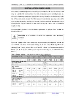
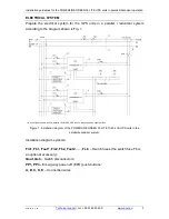
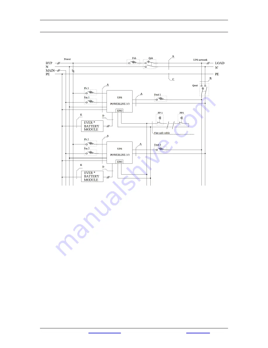
ELECTRICAL SYSTEM
Prepare the electrical system for the UPS units in a parallel / reduntant system
according to the diagram shown in Fig. 1.
* If a non-original module is used, install a 100 A / 440 V DC fuse on the positive and negative lines.
Figure 1. Installation diagram of the POWERLINE GREEN 33 LITE 10-60 kVA UPS units in the
parallel/redundant system.
Installation diagram symbols:
Fm1, Fb1, Fout1, Fm2, Fb2, Fout2, … , Fsb
– Switch fuses (the switch fuse Fb is
an optional accessory);
Qout, Qsb
– Switch disconnectors;
PP1, PP3
– Emergency power-off (EPO) push-buttons;
A, B, C, D, E
–
Connection wires.
Содержание POWERLINE GREEN 33 LITE
Страница 1: ......


