background image

2

NOTE

The words “Shall” or Must” indicate a requirement which is

essential to satisfactory and safe product performance.
The words “Should” or “May” indicate a recommendation

or advice which is not essential and not required but which

may be useful or helpful.

WARRANTY AND RESPONSIBILITIES

It is the sole responsibility of the home owner to make cer-

tain that the gas furnace has been correctly set up and con-

verted to the proper fuel (Propane or Nat. gas) and ad-

justed to operate properly.
Evcon Industries, Inc. warrants the furnace to be free from

defects in material or workmanship for a period of one year

(see warranty certificate packed with the furnace).
However, Evcon Industries, Inc. will not be responsible for

any repair costs to correct problems due to improper set---

up, improper installation, furnace adjustments, improper

operating procedure by the user, etc.
Some specific examples of service calls which cannot be

included in warranty payments are:

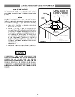
CONVERTING THE FURNACE TO USE ANOTHER

TYPE OF GAS.

1. Correcting faulty duct work in the home.
2. Correcting wiring problems in the electrical circuit to the

furnace.

3. Resetting circuit breakers or other switches.
4. Adjusting the burner air shutter or service calls made to

correct problems caused by improper air adjustment.

5. Correcting problems due to improper gas supply pres-

sure to the furnace.

6. Instructional training on how to light and operate fur-

nace.

7. Furnace problems caused by installation of air condi-

tioner, heat pump, or other air quality device which is not

approved.

8. Problems due to improper installation of the furnace flue

assembly (roof jack).

You should establish a

firm

understanding of these re-

sponsibilities with your manufactured housing dealer, ser-

vice company or gas supplier so there will be no misunder-

standing at a later time.

Gas Supply

CAUTION

Before placing furnace in service, it must be

checked to make sure it is equipped for the type of

gas being used. The burner flame must also be ob-

served and adjusted if necessary. Failure to ob-

serve this caution may result in unsafe operation,

explosion, and/or fire or asphyxiation. See follow-

ing sections “Gas Supply” and “Combustion Air”.

The gas supply to your home will either be Nat. Gas or Pro-

pane gas (bottle gas). Your furnace will be factory equipped

to operate on only one of these two different gases.
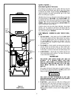
A small metal tag secured to the furnace just under the gas

valve will specify the type of gas your furnace is equipped

to use.
If the gas is different from that specified on the metal tag,

the furnace can be converted by following the instructions

on the furnace name plate. Parts for conversion are con-

tained in the small cloth bag attached to the gas valve. Be

sure the proper size orifice is used, as specified on the fur-

nace name plate.

CAUTION

The furnace must be converted by a qualified tech-

nician. Improper conversion can cause unsafe op-

eration, explosion, and/or fire or asphyxiation.

For Nat. gas operation the furnace is designed for 7” W.C.

inlet pressure. Pressure is reduced to 3---1/2” W.C. by the

pressure regulator in the gas valve.
For Propane gas, pressure at the gas valve must be 11”

W.C. When the gas valve is properly converted to Propane

gas, the pressure regulator in the gas valve is blocked

open, and the pressure is regulated at 11” W.C. by the reg-

ulator on the Propane gas tank. Consequently, the regula-

tor at the Propane tank may require adjustment.

CAUTION

If the gas input to the furnace is too great because

of excessive gas pressure, wrong size orifice, high

altitude, etc., the burner flame will be sooty and

may produce carbon monoxide, which could result

in unsafe operation, explosion, and/or fire or as-

phyxiation.

Never remove or block open the burner observa-

tion cover on the furnace. To do so may cause car-

bon monoxide to be drawn into the living space and

may cause asphyxiation.

OBSERVING BURNER OPERATION

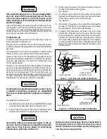
1. Observe burner to make sure it ignites. Observe color

of flame. On Nat. gas the flame will burn blue with ap-

preciably yellow tips. On Propane gas a yellow flame

may be expected. If flame is not the proper color call a

qualified serviceman for service.

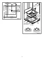
See Figures 2 and 3.

2. Let furnace heat until blower cycles on.
3. Turn thermostat down.
4. Observe burner to make sure it shuts off.
5. Let the furnace cool and blower cycle off.

Содержание DGAM Series

Страница 1: ...ll find obsolete parts In same cases the parts may still be available but under a new part number In other cases a generic part may be suitable for use For help in finding parts please visit our part...

Страница 2: ...N TO INSTALLER DO NOT HI POT TEST THIS FURNACE IF HIGH POTENTIAL TESTS ARE REQUIRED ON THIS MANUFACTURED HOME THIS FURNACE MUST NOT BE SUBJECTED TO THE TEST MUST BE DIS CONNECTED FROM ALL ELECTRICAL W...

Страница 3: ...acking the vent system check the rain caps Insure they are not damaged tilted or crooked Do not twist crush or sit on the roof caps during installa tion Damaged roof caps will cause improper furnace o...

Страница 4: ...oper furnace operation The furnace will not heat properly and could result in explosion 3 After installing vent pipe on furnace top collar check to make sure there is no gap in back or side between th...

Страница 5: ...CONNECTORS 10 DLAS SERIES FURNACES 11 DGAT DGAM SERIES FURNACES 12 CONNECTING ROOF JACK TO FURNACE 13 ELECTRICAL WIRING 14 Thermostat Wiring Four Wire for Heating Cooling 15 Thermostat Wiring For Heat...

Страница 6: ...r Must indicate a requirement which is essential to satisfactory and safe product performance The words Should or May indicate a recommendation or advice which is not essential and not required but wh...

Страница 7: ...with current CSA stan dard CAN CGA Z240 4 2 Installation Requirements for Propane Appliances and Equipment in Recreation al Vehicles Unit electrical wiring and grounding shall comply with current CSA...

Страница 8: ...Figure 3 Application 1 b With two return air grilles in closet door the upper grille must have a minimum of 250 sq in of free area and must be placed in the upper half of the door so it is directly op...

Страница 9: ...perating at high heat ing speed and the closet door closed is to be not more negative than minus 0 05 inch water column J For floor return systems the mobile home manufactur er or installer shall affi...

Страница 10: ...STION AIR PIPE TO FURNACE COMBUSTION AIR COL LAR SCREW HOLES ARE PROVIDED IN THE PIPE AND COLLAR EXCESSIVELY LONG SCREWS MAY EXTEND TO FLUE PIPE AND PUNCTURE IT IF SUB STITUTE SCREWS ARE USED THEY MUS...

Страница 11: ...e dimensions f th fl 4000B7121 91 to 102 are from the floor to the top side of 4000B7141 99 to 120 to the top side of the roof 4000B7151 106 to 132 See Figure 7 4000B7171 143 to 173 See Figure 7 4000B...

Страница 12: ...l not be sufficient clearance to bend the tabs on two sides of the duct connector In such cases the tabs may be attached to the sides of the duct by using sheet metal screws or other suitable fasten e...

Страница 13: ...M CON NECTOR INTO DUCT CUT OUT 2 BEND BOTTOM TABS OVER AND ONTO THE UNDERNEATH DUCT SERVICE FOR IMPROVED AIR SEAL DUCT CONNECTOR FLANGES MAY BE SEALED TO THE SUB BASE WITH ALUMINUM DUCT TAPE Follow th...

Страница 14: ...hole and center floor cut out opening on template over duct Accurately cut floor cut out opening from tem plate mark floor opening remove template and cut floor on outside edge of marked line to allo...

Страница 15: ...S IN FURNACE BASE APPLICABLE TO POSITION OF DUCT CONNECTOR TO FAS TEN DUCT CONNECTOR Figure 12 SECURE DUCT CONNECTOR TO FURNACE BASE WITH 4 SCREWS REFRIGERANT LINE OPENING FURNACE BASE BEND TABS OF DU...

Страница 16: ...to the furnace combustion air collar using two 2 1 2 inch sheet metal screws Screw holes are provided in combustion air tube and furnace com bustion air collar See Figure 13 c Secure roof jack flashi...

Страница 17: ...Run the 120 volt supply through the opening in the side of the furnace Join the electrical supply wires with suitable connectors to the electrical supply leads in the junction box Replace the junctio...

Страница 18: ...ur conductor thermostat wiring to accommodate future air conditioning installations Thermostat wires at Furnace Control Box Connect to Condensing Unit Contactor Furnace Control Box Suitable connectors...

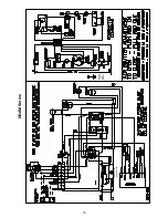
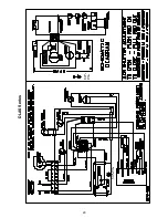
Страница 19: ...18 WIRING DIAGRAMS DGAT Series Ground Screw To Earth Ground Ground Screw to Earth Ground...

Страница 20: ...19 DGAM Series Ground Screw To Earth Ground Ground Screw to Earth Ground...

Страница 21: ...20 DLAS Series Ground Screw To Earth Ground Ground Screw to Earth Ground...

Страница 22: ...t more than 14 W C after furnace has been connected to fuel line Such testing could void the warranty Any test run above 14 W C may damage furnace control valve which could cause an explosion fire or...

Страница 23: ...9951 0861 NATURAL GAS 56 000 Input 70 000 Input 75 000 Input 95 000 Input Elevation Output Orifice Drill Part Output Orifice Drill Part Output Orifice Drill Part Output Orifice Drill Part 0 2000 Facto...

Страница 24: ...23...

Страница 25: ...24 LITHO IN U S A 3110 North Mead P O Box 19014 Wichita KS 67204 9014 Evcon Industries Inc 1973 081 Rev 2 8 94 P I Evcon...

Страница 26: ...8 9 11 12 13 14 2 15 45 43 42 41 39 32 33 31 34 16 17 18 10 23 1 3 5 4 30 CODE USED ON MODEL NO REQ PART NUMBER DESCRIPTION VENDOR __ All X 8B2461 Enamel Spray 15 oz Almond 1 All 1 4000 Series Roof Ja...

Страница 27: ...mit Switch O 145 C 115 EX 402 679 EX 402 680 30 All 1 7975 3771 A C Relay RBM 134 20103 301D 31 All 1 7970 5851 A Burner Assembly Less Gas Valve Includes Codes 12 13 17 32 All 1 1474 0521 Hot Surface...

Страница 28: ...this furnace or any of its components Never attempt to repair damaged or inoperable components Such action could cause unsafe operation explosion and or fire or asphyxiation If a malfunction has occur...

Страница 29: ...may result in unsafe operation explosion and or fire or asphyxiation See follow ing sections Gas Supply and Combustion Air The gas supply to your home will either be Nat Gas or Pro pane gas bottle gas...

Страница 30: ...eration explosion or asphyxi ation To adjust the combustion air 1 Allow the burner to burn for about 10 MINUTES To light and operate furnace see label on furnace door 2 Look through the pilot access d...

Страница 31: ...ircuit that powers the furnace controls and the blower motor The system switch must be turned ON for the furnace to operate Turn the switch to OFF when oiling the blower motor cleaning the blower etc...

Страница 32: ...or attempted repair may result D Do not use this appliance if any part has been under water Immediately call a qualified service technician to inspect the appliance and to replace any part of the cont...

Страница 33: ...on air supply to the burner causing inefficient burner operation and pilot outage When the temperature is very cold near zero or be low it is recommended that the roof jack be in spected every day or...

Страница 34: ...ted automatic damper P N 7900 6771 is available from fur nace manufacturer WARNING Fire or asphyxiation may result if wrong roof jack is applied or if the flue pipe and combustion air pipe have not be...

Страница 35: ...re is considered a part of the installation process and is required to make the furnace operate properly These furnaces are shipped from the factory with a natural gas orifice If you will be operating...

Отзывы: