


2
ESW4 Closed Circuit Coolers
Method of Shipment
ESW4 models are shipped with the top section(s) separate from the bottom section(s). These sections have mating flanges and
will join together in a waterproof joint when sealed and bolted together as described in the following instructions. Miscellaneous
items, such as sealer tape, hardware and any other required materials, are packaged and placed inside the pan for shipment.
For 8.5’ (2.6m) wide units, the motors and drives are factory aligned and then shipped loose inside the basin section for mounting
during installation. Refer to the “External Motor Installation” section in this bulletin.
Storage
Do not place tarps or other coverings over the top of the units if the units are to be stored before installation. Excessive heat can
build up if the units are covered, causing possible damage to the PVC eliminators, louvers or fill. For extended storage beyond six
months rotate the fan and fan motor shaft(s) monthly. Also, the fan shaft bearings should be purged and regreased prior to start-up.
International Building Code Provisions
The International Building Code (IBC) is a comprehensive set of regulations addressing the structural design and installation
requirements for building systems – including HVAC and industrial refrigeration equipment. As of June 2008, all 50 states plus
Washington D.C have adopted the International Building Code. The code provisions require that evaporative cooling equipment
and all other components permanently installed on a structure must meet the same seismic design criteria as the building.
All items attached to the Evapco ESW4 Closed Circuit Cooler must be independently reviewed and isolated to meet applicable
wind and seismic loads. This includes piping, ductwork, conduit, and electrical connections. These items must be flexibly attached
to the Evapco unit so as not to transmit additional loads to the equipment as a result of seismic or wind forces.
Structural Steel Support
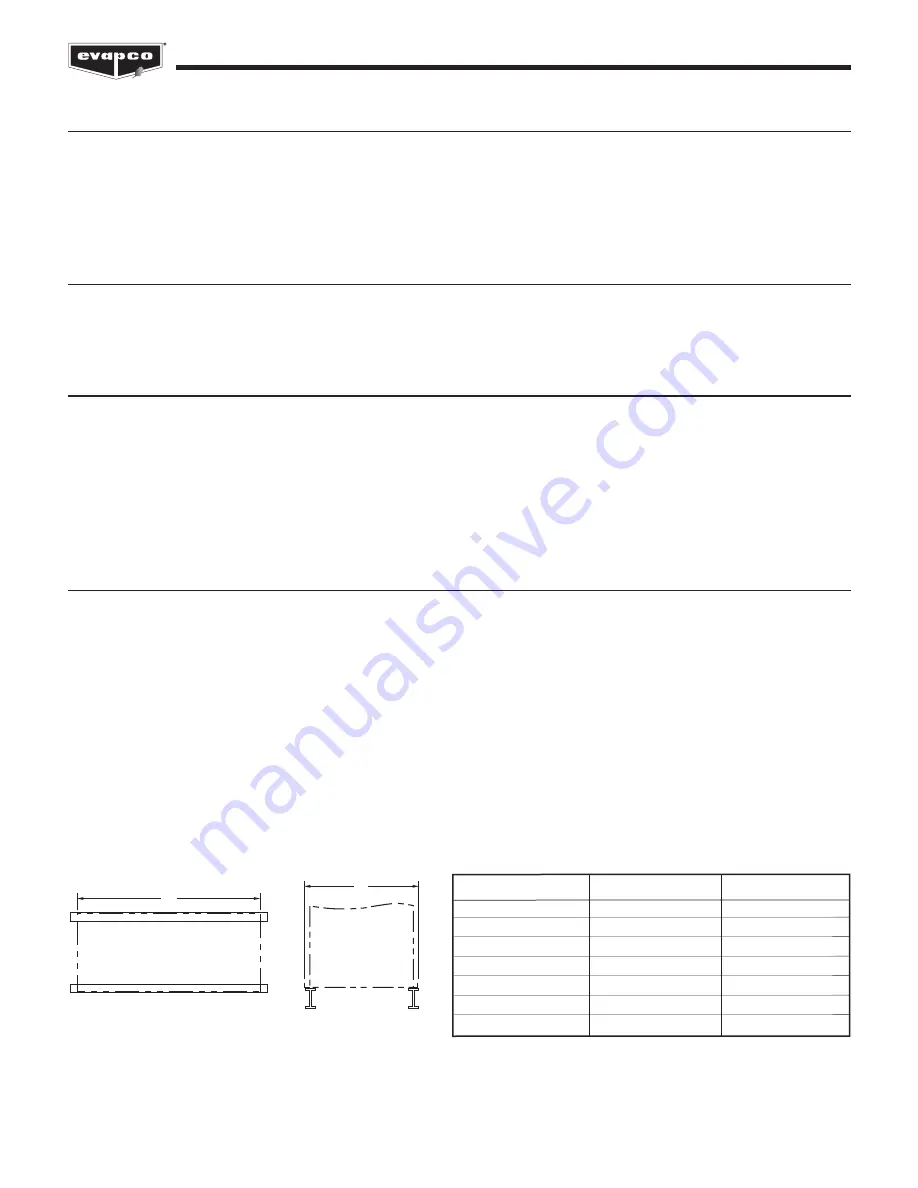
Evapco recommends supporting the unit with two structural “I” beams that span the entire length of the unit*. These beams should
be located underneath the outer flanges of the unit. (See Figure 1). Mounting holes, 3/4” (19mm) in diameter, are located in the
bottom flange for bolting to the structural steel (see certified print for exact bolt hole location). Bolt the bottom section to the steel
support before rigging the top section.
Beams should be sized in accordance with accepted structural practices. Maximum deflection of the beam under the unit not to
exceed 1/2” (13mm). Deflection may be calculated by using 55% of the operating weight as a uniform load on each beam (see
certified print for operating weight).
The supporting “I” beams should be level before setting the unit. Do not level the unit by shimming between the bottom flange and
the beams as this will not provide proper longitudinal support.
Support beams and anchor bolts are to be furnished by others. Always refer to certified print for unit weights, dimensions and
technical data.
Note: Consult IBC for required steel support layout and structural design.
Figure 1A
Plan Views
Figure 1B
End Elevations
A
8.5' to 14' WIDE
MODELS
B
8.5' to 14'
WIDE
MODELS
* The Engineer of Record is ultimately responsible for the steel support design and may require additional cross beams based on loads.
Unit Footprint
A
B
8.5' x 6' (2.6m x 1.8m)
8' 5-1/2" (2,578mm)
5' 11-7/8" (1,826mm)
8.5' x 9' (2.6m x 2.7m)
8' 11-1/2" (2,731mm)
8' 5-1/2" (2,578mm)
8.5' x 12' (2.6m x 3.6m) 11' 11-3/4" (3,651mm) 8' 5-1/2" (2,578mm)
8.5' x 18' (2.6m x 5.5m)
18' 0" (5,486mm)
8' 5-1/2" (2,578mm)
12' x 12' (3.6m x 3.6m) 11' 11-3/4" (3,651mm)
11' 10" (3,607mm)
12' x 18' (3.6m x 5.5m)
18' 0" (5,486mm)
11' 10" (3,607mm)
14' X 22' (4.2m X 6.7m) 21' 11-3/4" (6,700mm) 13' 11-1/4" (4,250mm)
Table 1
– ESW4 Supporting Steel Dimensions


