background image

24

Controller User Manual

The probe type connected to universal input U1.

The process value of the lower reading used to establish a

scale. This is not required for all sensor types.
The process value of the upper reading used to establish a

scale. This is not required for all sensor types.
The amount of time that is allowed to elapse after the

connection to the sensor is lost before an alarm is generated.

NTC if Dry Cooler 

4-20 mA if Condenser
Various

Various

60 seconds

Parameter

Description

Default

Table 8

The parameters associated with the process sensor.

Probe Type

Minimum Value

Maximum Value

Alarm Delay

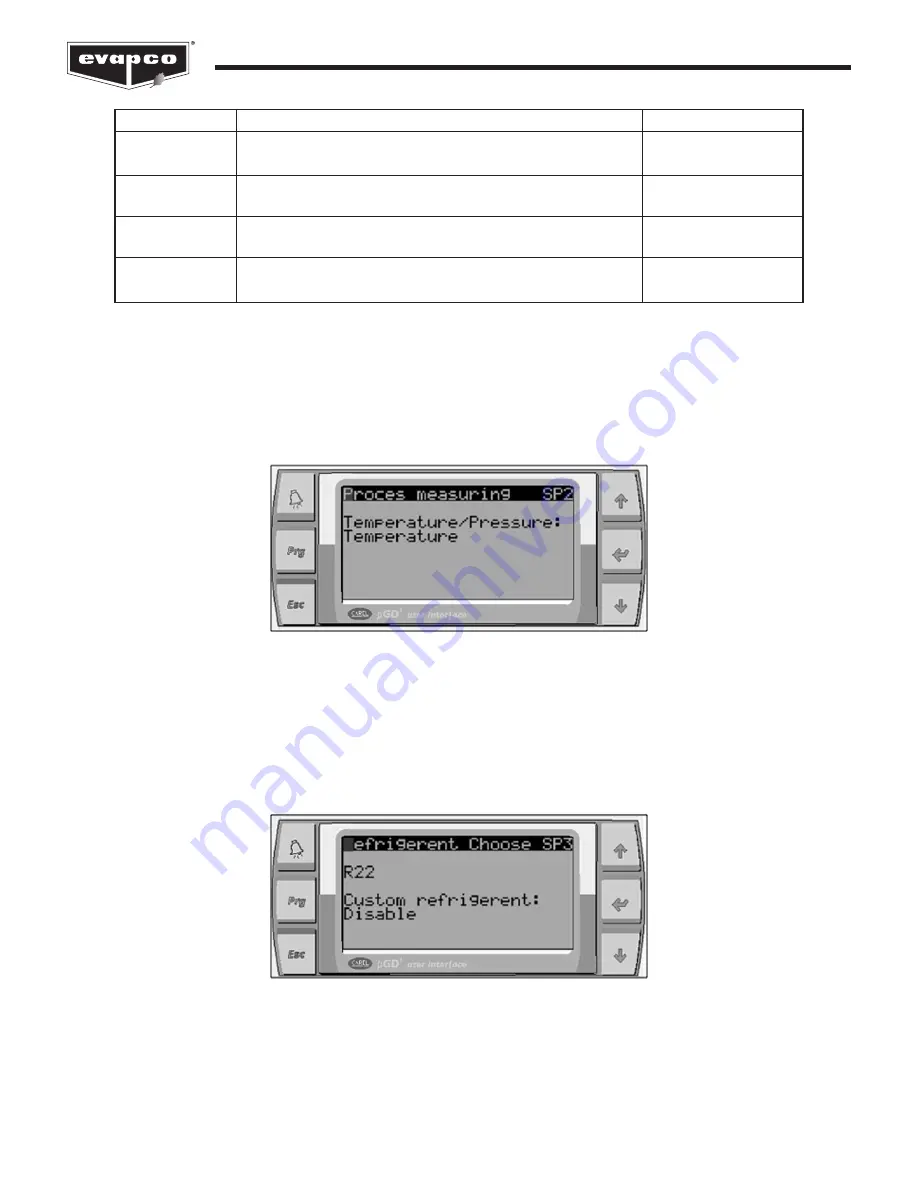
Figure 42

The process measuring is set as temperature in this example.

The screen shown in Figure 42 allows the user to determine if the process sensor is measuring a temperature value or a

pressure value. Note that this setting will be set at the factory and should not require modification. For fluid coolers, the default

setting will be 

Temperature

and for condensers the default setting will be 

Pressure

Figure 43

The refrigerant is chosen as R22 in this example.

If the eco-Air unit is a condenser, and the process measuring is set as 

Pressure

in Figure 42, the screen shown in Figure 43 will

be shown. When the EVAPCO Controller ships from the factory, the proper refrigerant for the application is already

programmed. Refer to Table 9 for a list of the available refrigerants. If the desired refrigerant is not listed in Table 9, a custom

refrigerant may be selected by selecting 

Enable

.

Содержание Eco-Air

Страница 1: ...l lvaro Obreg n Ciudad de M xico D F M xico 01090 Phone 52 55 8421 9260 e mail info evapco blct com Refrigeration Valves Systems Corporation A wholly owned subsidiary of EVAPCO Inc Bryan TX USA 979 77...

Страница 2: ...cing 6 Screen Navigation 7 Navigating the Display 7 Modifying a Value 8 Navigating the Scheduler 9 Operator Interface Screens 13 Welcome Screen 13 Standby Status Screens 13 Alarms Screen 16 Main Menu...

Страница 3: ...d require any additional information about the operation or maintenance of this equipment contact your local EVAPCO representative You may also visit www evapco com for more information Installation a...

Страница 4: ...n electrical disconnect for the eco Air unit Otherwise separate electrical disconnects may be required Consult applicable electrical codes to make this determination Avoid mounting the EVAPCO Controll...

Страница 5: ...d temperature or pressure sensor must be wired to the EVAPCO Controller Consult the supplied wiring diagram for a determination if the junction box is supplied Each EVAPCO Controller is supplied with...

Страница 6: ...ch position is as follows Auto The Auto position allows the EVAPCO Controller to operate the eco Air unit based on the logic programmed into the Controller Note that the unit must be switched on befor...

Страница 7: ...NT button Goes to the selected submenu or accepts a modified value DOWN button Scrolls down in the menu or changes a value Screen Navigation Navigating the Display The operator interface contains a LE...

Страница 8: ...Alarms Screen Standby Screen Standby Status Screens Main Menu Screens A On Off Unit B View Setpoints C Clock Scheduler D Input Output E Error Log F Board Switch G Service H Manufacturer Figure 5 Cont...

Страница 9: ...screen Figure 8 The cursor is located in the top left of the screen Navigating the Scheduler Several functions of the EVAPCO Controller are able to be scheduled to operate during certain periods of th...

Страница 10: ...et Mode during the selected period of time The selected block will become raised indicating that the Quiet Mode will be active Press the ENT button to move to the next half hour period 12 30am to 1 00...

Страница 11: ...ENT button After a few seconds the YES will change back to a NO indicating that the copy was successful Place the cursor next to the text that says MON Press the UP or DOWN button to change the day to...

Страница 12: ...User Manual Repeat the steps above until the desired scheduled is set Below is what the schedule of each day of the week should be for this example Figure 16 The Quiet Mode weekly schedule for the pre...

Страница 13: ...atus Screens are read only To view additional status screens use the UP or DOWN buttons located on the operator interface The Standby Screen shown in Figure 18 displays the process temperature ambient...

Страница 14: ...on to go directly to the Alarms Screen When the eco Air unit is equipped with EC fan motors the status and current speed of the fan motors may be viewed by pressing the DOWN button Figure 19 Standby S...

Страница 15: ...ined value the pre cooling system will activate Conversely if the process temperature falls below the process setpoint while the pre cooling system is active the decrease timer will begin to count up...

Страница 16: ...pre cooling system is activated stage two will be activated first followed by stage one Figure 26 Press the ENT button at this screen to view the alarm log All alarms are logged and are viewable by p...

Страница 17: ...co Air unit When the eco Air unit is not controlled via an external source i e BAS the On Off Unit Screen is the only way to disable the eco Air unit without removing power Note that the EVAPCO Contro...

Страница 18: ...s that may have been sucked onto the adiabatic pads during unit operation Routine Function Example Use Table 5 The various functions that may be scheduled hourly Quiet Mode Setpoint 2 Flush For instru...

Страница 19: ...time that the fans run in reverse during the flushing routine The fan speed reverse during the dry cycle of the flushing routine 0 minutes 0 minutes 0 Parameter Description Default Table 6 The flushin...

Страница 20: ...to ensure proper time keeping the daylight savings adjustment must be accurate Any adjustments to the daylight savings transition parameters may be done on the screen shown in Figure 33 Input Output S...

Страница 21: ...e alarm identifier number the alarm number in the log the date of the alarm and the time of the alarm For instructions on how to clear the alarm log please see the Alarms Screen section of this docume...

Страница 22: ...1 in the first position Next press the ENT button to move to the second position If incorrect password is entered the screen shown in Figure 37 is displayed Figure 37 The message displayed when an in...

Страница 23: ...nit to be adjusted The screen shown in Figure 41 allows the process sensor to be changed Note that the proper sensor type and associated settings will be set at the factory and should not require modi...

Страница 24: ...et as temperature in this example The screen shown in Figure 42 allows the user to determine if the process sensor is measuring a temperature value or a pressure value Note that this setting will be s...

Страница 25: ...stom refrigerant is required the temperature and pressure parameters may be entered on the screen shown in Figure 44 The seven data points describe the characteristics of the desired refrigerant and a...

Страница 26: ...Regulator Parameters Screen The screen shown in Figure 47 is only visible if the P regulator is chosen Controls the fan speed by subtracting the process temperature from the setpoint temperature and l...

Страница 27: ...e Setpoint 1 Temperature Regulation Band Minimum Fan Speed Maximum Fan Speed The primary process setpoint The secondary process setpoint that may be activated via the scheduler ambient temperature or...

Страница 28: ...ipped with a pre cooling system The energy saving fan speed allows the pre cooling system to activate once the fan speed reaches the energy saving value Once the pre cooling system is activated the fa...

Страница 29: ...g is not required Table 15 The stage switch point parameters The maximum speed that the fan motors will reach when Quiet Mode is not active The maximum fan motor speed allowed when Quiet Mode is activ...

Страница 30: ...oling system to be active If the ambient temperature falls below the minimum specified temperature the pre cooling system will deactivate and will not become active again until the ambient temperature...

Страница 31: ...m minimum operating ambient temperatures Setpoint Difference The following feature is only applicable for eco Air units that are equipped with EC fan motors In the event that the EC fan motors lose co...

Страница 32: ...active when the ambient temperature is 60 0 F with a differential temperature of 1 0 F Until the ambient temperature reaches 61 0 F the ambient setpoint plus the differential the primary setpoint will...

Страница 33: ...the building management method of control are desired to be utilized By default the EVAPCO Controller will be set to local control via the operator interface Note that is possible to use a building ma...

Страница 34: ...lity to maintain a specific process setpoint The Analog Output of Fans Screen allows the fan speed to be manually adjusted to any speed between 0 and 100 once the Manual Management function is enabled...

Страница 35: ...gic such as minimum ambient temperature and minimum on time once activated Enables or disables the manual fan speed The manual fan speed setpoint Disable 0 Manual Management Manual Speed Description D...

Страница 36: ...Manual Overrides Screen Figure 63 The Modbus Parameter Configuration Screen Within the service settings submenu there are several screens that allow for the adjustment of the working hours and sensor...

Страница 37: ...ith a linear offset if required via the screen shown in Figure 65 Figure 64 The Working Hours Set Screen Figure 65 The Probe Adjustment Screen The error log shown in Figure 35 may be cleared via the s...

Страница 38: ...rd shown on the screen is the current password The information screens display contain version details about the program loaded into the EVAPCO Controller and about the EVAPCO Controller itself This i...

Страница 39: ...needs to be replaced Use the UP or DOWN buttons to navigate between the different fan addresses Next set the current address to 1 and set change now to YES After a several minutes several messages wi...

Страница 40: ...troller User Manual Manufacturer Screens The Manufacturer Screens are for use by EVAPCO authorized factory technicians to configure the EVAPCO Controller Figure 72 The manufacturer menu within the mai...

Страница 41: ...sed in industrial control systems By adjusting control outputs a PID controller attempts to minimize the difference between a measured process variable and a desired setpoint PLC Programmable Logic Co...

Страница 42: ...ble to communicate with EC fan motor 8 The controller is unable to communicate with EC fan motor 9 The controller is unable to communicate with EC fan motor 10 The controller is unable to communicate...

Страница 43: ...43 Controller User Manual Notes...

Страница 44: ...EVAPCO Inc P O Box 1300 Westminster MD 21158 USA PHONE 410 756 2600 FAX 410 756 6450 E MAIL marketing evapco com 2018 EVAPCO Inc for LIFE Printed on recycled paper using soy based ink...

Отзывы: