


ESM-2850
30 ESM-2850 User’s Manual
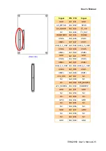
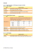
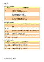
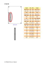
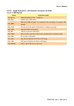
2.4.2.1.6 Miscellaneous Signals
Signal
Signal Description
I
2
C_CK
General purpose I
2
C port clock output
I
2
C_DAT
General purpose I
2
C port data I/O line
SPKR
Output for audio enunciator - the "speaker" in PC-AT systems
BIOS_DISABLE#
Module BIOS disable input. Pull low to disable module BIOS. Used to allow
off-module BIOS implementations.
KB_RST#
Input to module from (optional) external keyboard controller that can force a reset.
Pulled high on the module. This is a legacy artifact of the PC-AT.
KB_A20GATE
Input to module from (optional) external keyboard controller that can be used to
control the CPU A20 gate line. The A20GATE restricts the memory access to the
bottom megabyte and is a legacy artifact of the PC-AT. Pulled low on the module.
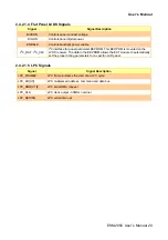
2.4.2.1.7 PCI Express Signals
Signal
Signal Description
PCIE_TX[0:2] +/-
PCI Express Differential Transmit Pair 0-2
PCIE_RX[0:2] +/-
PCI Express Differential Receive Pair 0-2
PCIE0/-
Reference clock output for PCI Express lanes 0-7 and for PCI Express Graphics
lanes 0-15
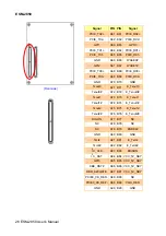
2.4.2.1.8 Power Signals
Signal
Signal Description
VCC_5V_SBY
Standby power input: +5.0V nominal. See Electrical Specifications for allowable
input range. If VCC5_SBY is used, all available VCC_5V_SBY pins on the
connector(s) must be used. Only used for standby and suspend functions. May be
left unconnected if these functions are not used in the system design.
VCC_RTC
Real-time clock circuit-power input. Nom3.0V. See Electrical Specifications
section for details.
Содержание ESM-2850
Страница 17: ...User s Manual ESM 2850 User s Manual 17 2 Hardware Configuration ...
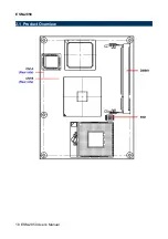
Страница 18: ...ESM 2850 18 ESM 2850 User s Manual 2 1 Product Overview ...
Страница 39: ...User s Manual ESM 2850 User s Manual 39 3 BIOS Setup ...
Страница 73: ...User s Manual ESM 2850 User s Manual 73 5 Measurement Drawing ...
Страница 74: ...ESM 2850 74 ESM 2850 User s Manual Unit mm ...
Страница 76: ...ESM 2850 76 ESM 2850 User s Manual Appendix B AWARD BIOS POST Messages ...


