1. Panel Illustration
1.1 Wireless ADSL2+ Router Front Panel Indicators and Descriptions
Place the Router in a location that permits an easy view of the LED indicators shown in the
front panel.
Descriptions of LED status
PWR
When an active power adapter is connected with router, this LED will light up.
WLAN
When WLAN card installed properly, this LED will be flashing. When transferring data,
the LED will be steadily.
ADSL
When connection with Internet (ADSL Connected) is established, this LED will light up.
When this LED is flashing: NO ADSL physical connection
X1
When port 1 connection with end user is established, this LED will light up.
X2
When port 2 connection with end user is established, this LED will light up.
X3
When port 3 connection with end user is established, this LED will light up.
X4
When port 4 connection with end user is established, this LED will light up.
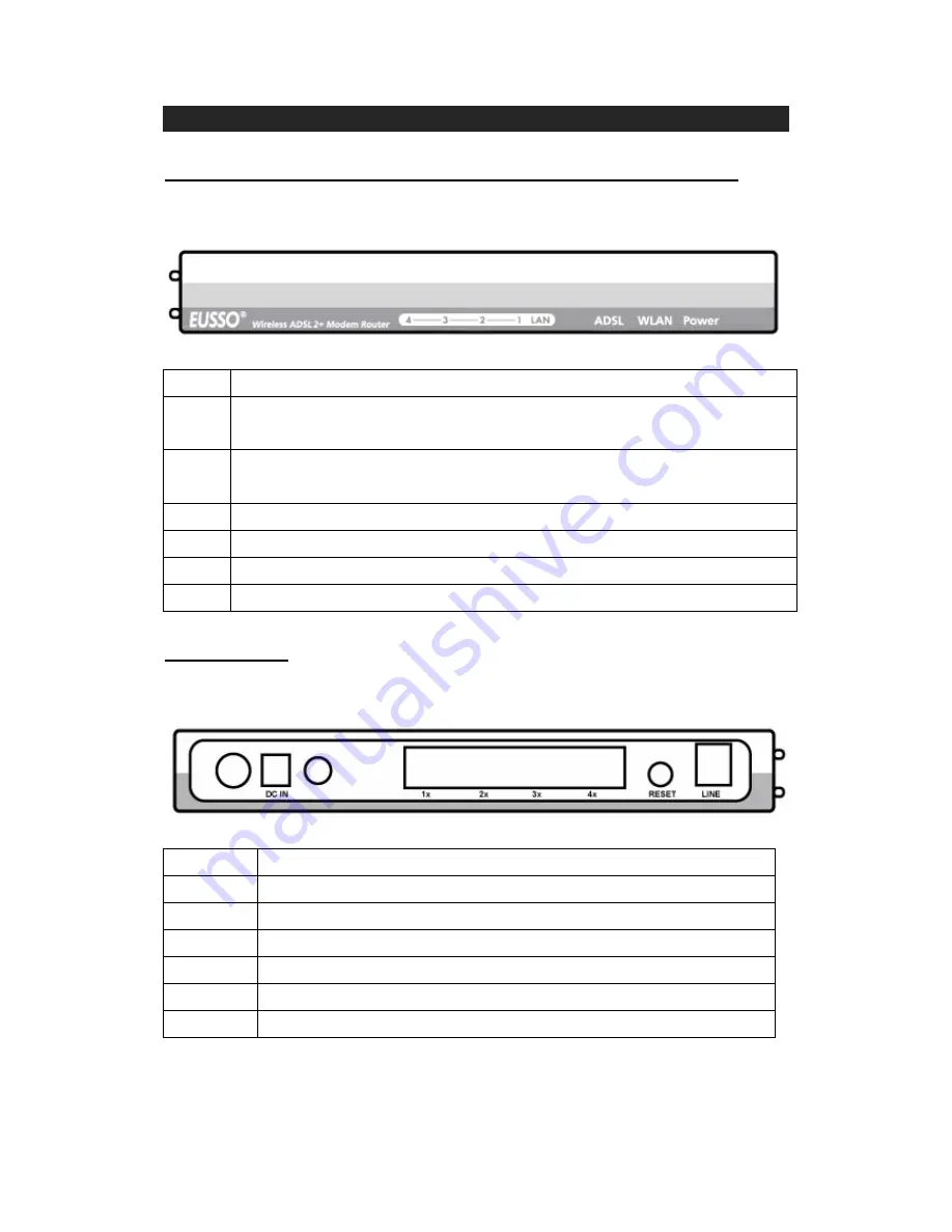
1.2 Back Panel
The back panel of the Router provides access to the power adapter cord connection as
well as the port connections.
Descriptions of All Connectors
LINE
Connect with phone cable
RESET
Reset button. Reset the setting to default.
4x
Connect with Ethernet Cable to Switch Hub or PC
3x
Connect with Ethernet Cable to Switch Hub or PC
2x
Connect with Ethernet Cable to Switch Hub or PC
1x
Connect with Ethernet Cable to Switch Hub or PC
DC IN
Connect to DC Power Adapter
2