


&KDSWHU
#<####
0DLQWHQDQFH
#
DQG
#
6HUYLFLQJ
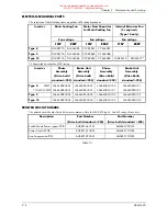
<#0#7
8;7
6
2953
35,17('
#
&,5&8,7
#
%2$5'
#+
3&%
,#
5(3/$&(0(17
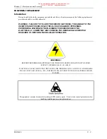
Observe all electrical warnings and static handling precautions at the front of this section - ‘Component
Replacement’
3URFHGXUH
3RZHU
#
&RQWURO
#
3&%
/#
&$/,%5$7,21
#
FDUG
#
DQG
#
&RQWURO
#
3&%
#+8;7
6
2953,#
5HSODFHPHQW
3RZHU
#
&RQWURO
#
3&%
/#
&$/,%5$7,21
#
FDUG
#
DQG
#
&RQWURO
#
3&%
#+8;7
6
2953,#
5HSODFHPHQW
3RZHU
#
&RQWURO
#
3&%
/#
&$/,%5$7,21
#
FDUG
#
DQG
#
&RQWURO
#
3&%
#+8;7
6
2953,#
5HSODFHPHQW
3RZHU
#
&RQWURO
#
3&%
/#
&$/,%5$7,21
#
FDUG
#
DQG
#
&RQWURO
#
3&%
#+8;7
6
2953,#
5HSODFHPHQW
1111
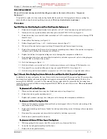
1.
Remove drive top and bottom terminal cover (plastic) via 2 off
¥
turn fasteners at top and bottom of drive
(see figure 1.1).
2.
Disconnect 30-way op-station ribbon cable from power control PCB CON 10 (see figure 9.1).
3.
Remove drive front cover (metal) which is attached via 4 off
¥
turn fasteners (take care not to damage PCBs
beneath cover).
4.
It is now possible to view the power control PCB, control PCB and cal card as shown in figure 9.1.
CON 5
CON 6
CON 7
1
2
3
CON 2
CON 3
CON 4
CON 10
DIAGNOSTIC LEDs
CON 8
CON 9
CAL CARD
CONTROL PCB
POWER
CONTROL
PCB
HINGED PANEL
HINGED PANEL FIXING
)LJXUH
#<14
5.
Take note of PCB connectivity and carefully remove and replace PCB, ensuring that PCB is re-connected
correctly.
6.
Replace drive front cover (metal) which is attached via 4 off
¥
turn fasteners (take care not to damage PCBs
beneath cover).
7.
Re-connect 30-way op-station ribbon cable to power control PCB CON 10 (see figure 9.1).
8.
Re-fit drive top and bottom terminal cover (plastic) via 2 off
¥
turn fasteners at top and bottom of drive.
This manual was downloaded on www.sdsdrives.com
+44 (0)117 938 1800 - [email protected]


