VULCAN Technical Manual
Detailed hardware description
© 2007 Eurotech Ltd Issue D
15
Detailed hardware description
The following section explains the functions that are included in the VULCAN. You may
need this information during development, when you start adding extra peripherals or
when you begin to use some of the embedded features.
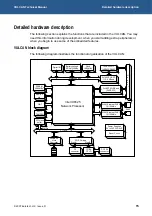
VULCAN block diagram
The following diagram illustrates the functional organisation of the VULCAN:
Intel IXP425
Network Processor
RJ45
33MHz
Expansion Bus
Digital I/O
Battery backed
SRAM 256KBy
Flash
16/32MBy
1xRS232/TTL
1xRS422/RS485
2x16550 UART
115.2 KBaud
H
e
a
d
e
r
WAN: Ethernet PHY0
10/100Mb/s
WAN: Ethernet PHY1
10/100Mb/s
2xUART 921KBaud
( 2xRS232)
Power Supplies
5V to 3V3/1V3/2V5
Reset Circuit
PCI BUS
SDRAM
32/64MBy
SERIAL
No
RTC +
TAMPER
4xUSB 2.0
Host
Controller
PCI clock
buffer
PCI/CF bridge
Slot A
Slot B
CF
connector
CF/ISA
CPLD
PC/104
connector
WDT
JTAG


