


www.eurolube.com
EUROLUBE EQUIPMENT AB
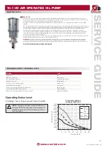
PART NO 15715
10:1 HV AIR OPERATED OIL PUMP
4
www.eurolube.com
17.Clamp the subassembly in a vise on the flats of the Nut [15]. Using an adjustable
17.
open-end wrench, loosen the Detent Spool [20]. Separate all parts. Set aside all items
from steps 16 and 17 in a group. Disassembly of the Air Motor is now complete.
LOWER PUMP DIsAssEMBLY PROcEDURE:
FiGUrE 10
Clamp the subassembly shown in figure 10 in a bench vise, holding the parts at the flat
1.
edge of the flange of the Fluid Adapter [38]. Using a strap wrench, apply torque to the
Pump Tube [51] to loosen and remove the Pump Tube and adjacent attached parts.
Set these parts aside after removal.
FiGUrE 9
With the Fluid Adapter [38] still clamped in the bench vise, remove the Fluid Piston
2.
[48], Pump Rod [50] and associated attached parts by sliding them out of the Adapter
[38]. Use care to avoid scarring the surface finish on the o.d. of the Pump Rod. Set
aside the Rod and Piston parts.
FiGUrE 8
Using snap ring pliers, remove the Retaining Ring [46] from the Fluid Adapter [38].
3.
Then remove the Cup Seal [44] and Wear Band [45]. Remove the O-Ring from the
lower i.d. of the Fluid Adapter [38]. Remove the Fluid Adapter from the bench vise. Set
all parts aside from figure 8 as a group.
FiGUrE 7
Clamp the Foot Valve Seat [39] in a bench vise. Using a strap wrench, loosen and
4.
remove the Pump Tube [51]. Using a pointed tool, push out the Pin [41], then remove
the ball [40] and O-Ring Seal [43]. Set all parts aside from figure 7 as a group.
FiGUrE 6
Clamp the Pump Rod [50] in a bench vise. Note! Use Split wooden vise blocks
5.
matched to the Pump Rod diameter to prevent scarring the Rod surface! Remove
the Wear Band [47] and O-Ring Seal [49]. Then, using a spanner wrench, loosen and
remove the Fluid Piston [48]. It is not necessary to remove check valve parts internal
to the Fluid Piston. If they are damaged or malfunctioning the entire assembly must be
replaced. Set all parts aside. Disassembly of the Pump Lower is now complete.
LOWER PUMP AssEMBLY PROcEDURE
FiGUrE 6
Collect the parts group shown in figure 6. Substitute rebuild kit parts in place of old
1.
items where applicable. Clamp the Pump Rod [50] in a bench vise. Note! Use Split
wooden vise blocks matched to the Pump Rod diameter to prevent scarring the Rod
surface! Insert the Ball [40] into the cavity of the Pump Rod [50], apply Loctite thread
lock to the o.d. threads of the Fluid Piston, then screw the Fluid Piston [48] into the
Pump Rod [50] Tighten using a spanner wrench, to approximately 20 ft-lb torque.
Apply a film of grease to the o.d. grooves of the Fluid Piston [48]. Install the Wear Band
2.
[47] and O-Ring Seal [49]. Set this subassembly aside.
FiGUrE 7
Collect the parts group shown in figure 7. Substitute rebuild kit parts in place of old
3.
items where applicable. Install the O-Ring Seal [43] on the o.d. shoulder of the Foot
Valve Seat [39]. Install the Ball [40] and Pin [41]. Clamp the Foot Valve Seat [39] in a
bench vise. Using a strap wrench, install and tighten the Pump Tube [51] to approxi-
mately 20 ft-lb. torque. Set this subassembly aside.
FiGUrE 8
Collect the parts group shown in figure 8. Substitute rebuild kit parts in place of old
4.
items where applicable. Clamp the Fluid Adapter [38] in a bench vise, gripping the
edges of the flange, with rod cavity horizontal. Install the O-Ring Seal [42] on the i.d.
shoulder of the Fluid Adapter [38]. Install the Cup Seal [44] and Wear Band [45] in
the seal cavity of the Adapter. Note! cup seal lips point down, away from the adapter
flange. Using snap ring pliers, install the Retaining Ring [46] into the Fluid Adapter [38]
groove.
FiGUrE 9
With the Fluid Adapter [38] still clamped in the bench vise, install the Fluid Piston [48],
5.
Pump Rod [50] and associated attached parts from lower pump assembly step 2, by
sliding them into the Adapter [38]. Use care to avoid scarring the surface finish on the
o.d. of the Pump Rod.
FiGUrE 10
With the Fluid Adapter [38] still clamped in the bench vise, install parts previously
6.
combined in lower pump assembly step 3. Using a strap wrench, apply torque to the
Foot Valve Seat [39] and tighten to 40 ft-lb torque. Lower Pump Assembly is now
complete.
AIR MOTOR AssEMBLY PROcEDURE
FiGUrE 2
Collect the parts group shown in figure 2. Substitute rebuild kit parts in place of old
1.
items where applicable. Install the Valve Bar [21] on the mating diameter of the Detent
Spool [20]. Clamp the 5/8” Jam Nut [15] in a bench vise on the flats of the Nut and
apply Loctite 638 thread lock to the internal threads of the Jam Nut [15]. Then, Using
an adjustable open-end wrench, install and tighten the Detent Spool [20]. Apply 85
in-lb torque.
Install the Exhaust Valve Stems [23] into the Valve Bar [21]. Apply Loctite 638 thread
2.
lock to the internal threads of the 5/16” Jam Nuts [25] and install on the stems [23] and
tighten to 70 in-lbs using two open-end wrenches. It will be necessary to secure the
hex cap of the Valve Stem [23] with an open end wrench while securing the first nut.
Then install the O-Ring Seals [24] into the gland of the two Valve Stems [23].
FiGUrE 3
Secure the Rod Head [33] in a bench vise, clamping the part across the flats. Apply
3.
Loctite 271 to the internal threads. Install the Trip Rod [32] and tighten to 40 in-lb
torque. Use vise grips, applied near the Rod Head, to turn the Trip Rod.
Install the following items onto the Trip Rod [32] in the sequence and orientation
4.
shown in figure 3: Spring Retainer [14, qty=3], Trip Spring [15, qty=2], assembled
parts from stage 1, figure 2.
Apply Loctite 271 to the internal threads of the Spring Retainer, Threaded [34]. Install
5.
the Spring Retainer, Threaded on the end of the Trip Rod [32] and tighten the entire
assembly to 100 in-lbs torque.
FiGUrE 4
Clamp the Air Piston [18] in a vise, with clamping pressure applied to the 6” diameter
6.
on the piston. Note! Use Split wooden or elastic vise blocks matched to the piston
diameter to prevent scarring the piston surface!
Apply a film of grease in the center cavity of the Air Piston [18]. Insert the assembled
7.
parts from assembly stage 2 (per figure 3) into the cavity, oriented as shown in figure
4.
Apply a film of grease to the seal gland and o.d. surfaces of the Intake Valves [22].
8.
Install O-Ring Seals [24] on the Intake Valves. Then pass the valves through the ports
of the Air Piston [18] and into the mating holes on the Valve Bar [21]. Secure the Valves
with 5/16” Jam Nuts [25]. Tighten all Jam Nuts to 70 in-lb torque.
Apply a film of grease to the 1/2” Ball [27, qty=2] and Detent Spring [28, qty=2]. Then
9.
by hand, apply upward pulling force on the Trip Rod assembly, so that the intake
valves [22] are completely closed. With the Trip Rod held in that position, install the
1/2” Steel Ball [27], Detent Spring [28] and Detent Sleeve [29] in each of the two
detent ports located on the Air Piston [18]. It will be necessary to unclamp and adjust
position of the Air Piston during this procedure.
Apply a film of grease to the o.d. seal gland on the Air Piston [18], then install the O-
10.
Ring Seal [6]. Remove the Air piston from the vise and apply a film of grease to the 6”
diameter piston surface. Set aside the completed subassembly.
FiGUrE 5
Clamp the Upper Body in a bench vise, oriented with bore horizontal. Use elastic jaw
11.
cushions in the vise to prevent scarring the pump surface. Install the Air Motor Subas-
sembly [shown in figure 4] into the Upper Body [2]. Install from the top of the pump,
opposite the direction of the 1/2” NPT port on the Upper Body. Slide in carefully,
keeping the Air Piston square with the bore of the Upper Body.
Install the O-ring Seal [5] into the gland in the Cap [1]. Install the Cap [1] on the top of
12.
the Air Motor. When the Cap [1] is installed, it must be shifted sideways approximately
1 inch to allow attachment of the internal Rod Head [33, fig 2] into the slot on the Cap
[1].
Apply a film of grease to the seal glands on the Center Insert [3]. Install the two O-ring
13.
Seals, [5] and [26], in their glands on the Center Insert [3]. Install the Center Insert [3]
on the subassembly by sliding it gently onto the Air Piston.
If the 5/16” Threaded Studs [7, qty=4] and Acorn Nuts [11, qty=4] have become
14.
separated during subassembly, they must be reassembled with adhesive before
proceeding further. Clean and degrease the threads of the Stud and Nut. Apply Loctite
271 to the internal threads of the Acorn Nut [11] and install the Nut on the Stud [7].
Using vise-grip pliers to hold the Stud [7] near the Acorn Nut [11], tighten the Nut with
a hex wrench to 100 in-lb torque.
Install the Studs [7, qty=4] and Acorn Nuts [11, qty=4] as shown in figure 5, into the
15.
holes on the subassembly. Using a socket wrench, hold the 1/2” Hex Acorn Nut [11] on
the pump Cap [1]. With a second socket wrench, install and tighten the 1/2” Hex Nut
[10, qty=4] and Lock washer [9, qty=4] at the other end of the 1/2”-13 Threaded Stud
[7]. Leave the Upper Body clamped in the bench vise.
FINAL PUMP AssEMBLY PROcEDURE:
FiGUrE 11
Install the Lower Body [4] in position on the Air Motor (from figure 5), with Dowel Pins
16.
on the Lower Body oriented away from the Air Motor. Install the Muffler [17] and Dif-
fuser Plate [16] in the counterbore of the Lower Body [4].
Install the Bare Lower subassembly on the Air Motor as shown in figure 11. The muffler
17.
must be loosened, Pump Rod, muffler, and diffuser plate shifted off-center 1”, then
moved into position and the Pump Rod locked into the coupler slot on the bottom of
the Air Piston. After attachment to the Air Piston, reposition the muffler and diffuser
plate then move the flange of the Fluid Adapter into tight contact with the Lower Body.
Install the 5/16” Hex Cap Screws [13] and Lock washers [12], then tighten to 100 in-lb
torque. Pump assembly is complete.


