


www.eurolube.com
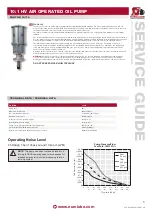
10:1 HV AIR OPERATED OIL PUMP
www.eurolube.com
EUROLUBE EQUIPMENT AB
PART NO 15715
10:1 HV AIR OPERATED OIL PUMP
3
PUMP INsTALLATION
PUMP OPERATION
PUMP REPAIR / sERVIcINg
Provide a drop-tee fitting, 3/4” size or larger, in the nearby air supply pipeline. From that tee, install the following pump air line assembly:
pipe bushing or adapter (to bring the line drop size to 3/4” male)
•
1/2” pipe drop to pump level
•
1/2” pipe elbow
•
1/2” air F-R-L
•
1/2” air shutoff ball valve (having an air relief vent when closed)
•
1/2” to 3/8” reducer and a 3/8” x 3 ft. air hose
•
3/8” air line coupler and nipple.
•
Attach the air nipple to the air inlet port of the pump. During assembly of the air supply line, be sure to clean out all foreign materials
before making connection to the pump. Eurolube recommends that an air line lubricator be used with turbine oil (viscosity 150-170 SSU @
37°F) and set at a maximum oil feed rate of 1 drop every 2 hours of pump operation. The pump air motor has been coated internally with a
special synthetic grease at initial assembly and does not require additional grease except during reassembly after a repair.
TO sTART PUMP:
Immerse the pump’s suction tube or fluid inlet into the fluid to be pumped.
1.
Connect the air coupler to the pump and turn the air regulator to the minimum setting.
2.
Direct pump outlet hose into an approved waste oil container.
3.
Slowly adjust the air regulator until the pump is primed and running smoothly. Be sure all air has been purged from the
4.
system. The pump should prime in less than 30 seconds.
Use the air regulator to control the pump’s speed and cycle rate. Always use the lowest pressure required to obtain the
5.
desired flow rate. This will increase pump and seal life.
Never allow a pump to be run dry of the fluid being pumped. A dry pump quickly speeds up, which could damage the
6.
air motor and fluid seals. If the pump suddenly speeds up, cut off the air supply as soon as possible, refill the system
fluid reservoir and reprime the pump.
If the pump will be unattended for any period of time, or to shut off the system at the end of a work shift, always follow
7.
the Pressure Relief Procedure on page 5 of this manual.
If the pump will be unattended for any period of time, or to shut off the system at the end of a work shift, always relieve
8.
the pump’s pressure.
PUMP DIsAssEMBLY PROcEDURE:
FiGUrE 11
Mount the pump horizontally in a bench vise. Clamp the vise to the upper body of the
1.
pump and use elastic jaw cushions in the vise to prevent scarring the pump surface.
With a socket wrench, loosen and remove the four lower 5/16” Hex Bolts [14] and Lock
Washers [12]. Then remove and set aside the Bare Lower subassembly. Also remove
the Lower Body [4], Muffler [17], and Diffuser Plate [16] .
If the air motor subassembly will not be repaired immediately, re-attach the Lower
2.
Body [4], Muffler [7], and Diffuser Plate [16] to the Air Motor subassembly, temporarily
securing them with the 5/16” Bolts [14] and Lock Washers [12], turned hand tight.
Remove the assembly from the vise.
For further disassembly, use the separate procedures which follow for the Air Motor
3.
and Lower Pump subassemblies.
AIR MOTOR DIsAssEMBLY PROcEDURE:
FiGUrE 5
If the Lower Body [4], Muffler [17], and Diffuser Plate [16] are attached to the Air Motor
4.
subassembly, remove them now, along with the four 5/16” Hex Bolts [14] and Lock
washers [12] which secure them.
Mount the Air Motor horizontally in a bench vise. Clamp the vise to the Upper Body
5.
[2] of the pump and use elastic jaw cushions in the vise to prevent scarring the pump
surface.
Using a socket wrench, hold the 1/2” Hex Acorn Nut [11] on the pump Cap [1]. With a
6.
second socket wrench, loosen and remove the 1/2” Hex Nut [10] and Lock washer [9]
at the other end of the 1/2”-13 Threaded Stud [7]. Then remove the Acorn Nut [11] and
Stud [7] as a group. Do not remove the Acorn Nut from the Threaded Stud. Repeat the
procedure for the other three Studs. Set aside all fasteners in a group.
Remove the Center Insert [3] from the subassembly by sliding it carefully off the Air
7.
Piston. Remove the two O-ring Seals, [5] and [26], from their glands on the Center
Insert [3]. Set these parts aside in a group.
Remove the Cap [1] from the top of the Air Motor. As the Cap [1] is removed, it must be
8.
shifted sideways approximately 1 inch to allow detachment from the internal Trip Rod.
After removal of the Cap, remove the O-ring Seal [5] from the gland in the Cap. Set
these parts aside in a group.
Remove the Air Motor Subassembly [shown in figure 4] from the Upper Body [2].
9.
Remove toward the top of the pump, opposite the direction of the 1/2” NPT port on
the Upper Body. Slide out carefully, keeping the Air Piston square with the bore of the
Upper Body. Remove the Upper body from the vise and set aside.
FiGUrE 4
Remove the O-Ring Seal [6] from the Air Piston [18]. Using a flat blade screwdriver,
10.
remove two Detent Sleeves [29], Detent Springs [28], and Detent Balls [27]. Set all of
the removed parts aside as a group.
Clamp the Air Piston in a vise applied to the 6” piston diameter. Note! Use Split wood-
11.
en vise blocks matched to the piston diameter to prevent scarring the piston surface!
Using two open-end wrenches, loosen the Jam Nuts [25] located on top of the Intake
12.
Valve Stems [22]. Remove the Jam Nuts and the two Intake Valve Stems. It may be
necessary to secure the hex cap of the Valve Stem [22] with an open end wrench while
removing the second nut. Then remove the O-Ring Seals [24] from the gland of the
two Valve Stems [22].
Remove the Valve Trip Assembly [shown in figure 3] from the top of the Air Piston.Re-
13.
move the Air Piston plus Rod Coupler, items [18] and [19], from the vise and set aside.
Note! It is not necessary to separate the joint of the Air Piston and Coupler.
FiGUrE 4
Secure the assembly horizontally in a bench vise, clamping the parts at the flats
14.
located on the Rod Head [33]. Applying torque to the flats of the Retainer, Spring,
Threaded [34], loosen the trip rod assembly. Note! Turn wrench slowly and steadily to
prevent breaking male threads on the Trip Rod [32].
Remove all parts from the Trip Rod [32]. Using vise-grip pliers, clamp the Trip Rod
15.
[32] near the Rod Head [33] and loosen the remaining threaded joint. Set aside all
loose parts in a group, but retain the Valve Bar parts [shown in Figure 2] for further
disassembly.
FiGUrE 2
Using two open-end wrenches, loosen the Jam Nuts [25] located on top of the
16.
Exhaust Valve Stems [23]. Remove the Jam Nuts and the two Exhaust Valve Stems.
It may be necessary to secure the hex cap of the Valve Stem [23] with an open end
wrench while removing the second nut. Then remove the O-Ring Seals [24] from the
gland of the two Valve Stems [23].
NOTE:
Pump performance will be degraded
by air or fluid threaded connections which are
not air-tight. Use Teflon™ tape or other suitable
means to achieve a complete thread seal.
WARNING:
Attach a proper ground wire to
the pump grounding lug (item 52, p.10) before
starting the pump.
!
!
CAUTION:
Read all limitations which apply
to selection of fluids which may be pumped by
this product. Do not pump a fluid which is not
specified to be compatible.
CAUTION:
Always read and follow fluid
manufacturers' recommendations regarding
proper use of protective eye wear, clothing
and respirators.
!
!


