


©
EUROHEAT
DISTRIBUTORS (H.B.S) LTD April 2007
23
E&OE Instructions Part Number IN1190 Ed B
H11##0105A
Commissioning
Remove coal effect before attempting commissioning .
Shortly after the stove is lit a stove air pressure
reading should be taken and the pressure monitored
at fifteen minute intervals to ensure the stove and flue
are operating safely with sufficient air. As the stove
and flue warm, the supply of air being induced into
the burner will increase, and it will be possible to raise
the stove’s firing rate progressively until the stove is
running at its maximum output.
(Note do not increase oil flow rate to the point where
smoke is produced)
The entire Stove, flue and boiler, if fitted, (if a boiler
is fitted to the stove the return temperature should
be at least 50°C) should be allowed to reach normal
operating temperature. Depending on the flue system
this may take 1-4 hours.
Commissioning without the system at operating
temperature will probably result in you the engineer
returning to correct the commissioning at a later date.
Reduce the control setting to No 1 (low setting).
After 5-10 minutes take a draught reading. This
reading should be within the requirements of the stove.
If the draught readings are higher than required see
section solving negative pressure problems.
Once the correct low fire chimney draught has been
achieved turn the stove to high fire No 6. Wait 10-15
minutes for the chimney draught to recover. Adjust
the draught stabilizer weight so the chimney draught
does not exceed the maximum required. If the draught
cannot be achieved for high fire see section reducing
high fire flow rates.
With the chimney draught settings correctly
set the oil flow rates need to be checked. This is
normally checked by the visual size of the flame.
The following flame size diagrams are to assist
with correct adjustments.
Low Fire (Minimum flame size)
Flue draught at maximum requirement for low fire No 1
setting i.e. 0.045”wg
The catalyser will glow brightly from its inner core of
vanes and with a dull red glow from its outer vanes,
with the only visible flames being horizontal blue
translucent jets dancing between the catalyser and
the holes in the burner cylinder wall.
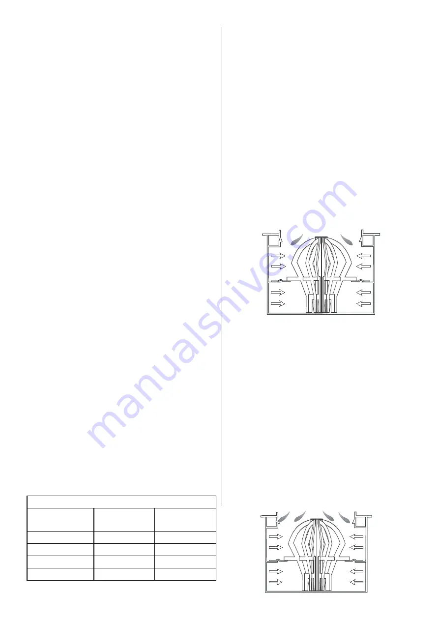
Low Fire
(Maximum flame minimum flue draught)
Flue draught at Minimum requirement for low fire No 1
setting i.e. 0.03”wg
The main body of the flame should be a translucent
ring, beginning from the top row of holes in the burner
body and finishing approximately 15mm above the
burner rim. The complete catalyser should be glowing
brightly with blue flame jets dancing horizontally
between the catalyser and the holes in the burner
cylinder wall. This setting will increase coal effect
operation.
If the flame size is larger than this decrease low fire
flow rate, if the flame size is smaller increase the oil
flow rate. (See adjusting oil valve).
Do not adjust more than 1/4 turn before allowing burner
to settle
Flow Rate Correction
Correct flame pattern with 8” or 10” burner
(Coal effect
removed)
No assessment of flame size or pattern should be
made until the stove and flue have reached full
operating temperature and the correct negative
pressure (chimney draught) within the stove has
been achieved. All adjustments to the oil metering
valve should be followed with a period of undisturbed
running before making any assessment and several
minutes should be allowed for the flue draft to stabilise
after adjusting the flue stabilizer.
Flow Rates
Model
Minimum
Flow
Maximum
Flow
Harmony 11
2.1cc
7.7cc
Harmony 21
2.5cc
10.5cc
Harmony 31
4.3cc
15.3cc
Harmony 41
5.3cc
20.0cc


