Eureka E51M Скачать руководство пользователя страница 19


19 


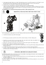
MOUNTING THE ABRASIVE DISC ONTO THE DISC PAD HOLDER 

The machine can operate with brushes or abrasive discs of various types mounted on special disc pad holders. 
Follow the instructions below to mount the abrasive disc onto the disc pad holder: 


1

2

3


4


Remove  the  disc  lock  (position  3)  from  the  disc  pad  holder  (position  1)  by  pressing  the  2  ends  of  the  spring  catch 
(position 4) against each other. 


Position the abrasive disc (position 2) and centre it onto the disc pad holder (position 1). 


Place  the  disc  lock  (position  3)  on  the  centre  and  press  down  hard  until  the  spring  fits  into  place  (position  4);  this 
operation can be carried out using the palm of your hand, or your foot if the disc pad holder is resting on the ground. 


MOUNTING THE BRUSH OR ABRASIVE DISC ON MACHINE  


Follow  the  instructions  below 

to  mount

  the  brush 

or disc pad holder with abrasive disc: 


Turn  off  the  machine  and  press  the  key  into 
position 0. 


Lift the brush plate (pos.3) with the pedal (pos.1). 


Put  the  inclination  of  the  brush  plate  into  0  position  by 
turning the brush adjusting knob (pos.2) clockwise. 


Position  the  brush  or  disc  pad  holder  (pos.5)  under  the 
brush  plate  lifting  the  splashguard  (pos.4)  and  centre  it 
with the plate.  


Slowly lower the brush plate with the pedal (pos.1).  


Go into drive position and move the machine from right to 
left  and  vice  versa  until  the  brush  fits  into  place  correctly 
on the centre of the plate.


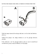
Rotate the key-operated switch (pos.1) and wait till the battery charge level is no more visible on 
the display. At this point the starting-up sequence is complete. 


Put the potentiometer for speed adjustment into min. position by pressing it towards the drawing 
of the turtle, on the label.  


Push the brush switch to activate the brush. The brush does not rotate when the green light is on. 


Slowly push forward the drive control and release it as soon as the brush starts rotating. The brush motor will rotate for 
2 seconds thus allowing for brush release. Repeat the same operation again if necessary.  


With the brush removed from the plate, move the brush plate back into its original position by means of the knob pos. 
2. Turn the knob clockwise (towards the sign +, on the label) for 4 rounds (inclination recommended).  


Lift the brush plate with pedal (pos. 1). 


Содержание E51M

Страница 1: ...M E61M _______________________________________________ EUREKA S p a Viale dell artigianato 30 32 35013 CITTADELLA PD ITALY Tel 39 049 9481800 Fax 39 049 9481899 INTERNET www eurekasweepers com E MAIL...

Страница 2: ...2...

Страница 3: ...22 OPERATION 23 PERIODIC SERVICING 24 DRAINING AND CLEANING THE RECOVERY TANK 24 DRAINING AND CLEANING THE SOLUTION TANK 25 CHECHING BRUSHES OR ABRASIVE DISCS 25 CLEANING REPLACING AND CHECKING THE IN...

Страница 4: ...ition These are normal maintenance measures that any operator will be able to carry out with implements that he or she should normally have in the company In the case of particularly demanding work pl...

Страница 5: ...OPERATE ADJUST CARRY OUT ORDINARY SERVICING CLEAN REPAIR AND TRANSPORT THE MACHINE OUR COMPANY WILL NOT BE HELD LIABLE FOR ANY PROBLEMS BREAKAGE ACCIDENTS OR OTHER OCCURRENCES DUE TO THE IGNORANCE OR...

Страница 6: ...ions have a look at the procedures shown in the various chapters Never collect pieces of string wire or anything else that could damage the brushes by winding around them Never suck up pieces of wood...

Страница 7: ...ty range of 30 80 PRECAUTIONS FOR THE SAFETY OF OPERATORS AND TECHNICIANS The machine must not be used by non authorised personnel who have not been trained to use it properly or by people who are und...

Страница 8: ...DISPOSAL OF THE RECOVERY SOLUTION TANK Prior to be moved on specific purification plants the recovery tank solution is to be disposed of in the appropriate sites TRANSPORT HANDLING TRANSPORT The mach...

Страница 9: ...Follow the instructions below to unpack the machine connect the inclined ramp position A to the front part of the pallet see figure 1 tilt the machine slightly and place the wheel lifting plate posit...

Страница 10: ...stop position in a flat surface area put on the brake and turn the key into position 0 Unblock the tank by means of the two levers pos 1 placed on both sides REACH THE DRIVER S POSITION AND LIFT THE T...

Страница 11: ...es suitable for the machine FIG C FIG B 2 3 FIG A L 250mm FIG B L 515 mm FIG C Follow the instructions below to mount the batteries to the machine park the machine on a flat surface put on the brake i...

Страница 12: ...4 Brush plate lift pedal 15 Recovery tank outlet pipe 16 Instrument panel inclination adjustment hand wheel 17 Anti crushing device 18 Level indicator pipe and solution tank outlet drain 19 Tap 20 Bat...

Страница 13: ...ustment hand wheel 14 Brush plate lift pedal 15 Recovery tank outlet pipe 16 Instrument panel inclination adjustment hand wheel 17 Anti crushing device 18 Level indicator pipe and solution tank outlet...

Страница 14: ...WHEEL Enables the instrument panel to be positioned in three different inclinations 3 ANTI CRUSHING DEVICE This is a safety device that halts the machine in reserve drive and makes it go forward for a...

Страница 15: ...mper inserted the charge indicator is set for lead acid batteries FIG A Without the jumper the charge indicator is set for gel agm batteries FIG B If the indicator is set for gel agm batteries and you...

Страница 16: ...ged When the red light comes on after about 20 seconds the brush motors will stop running Go to the charging zone and charge the battery Warning The indicator is configured for acid lead batteries To...

Страница 17: ...RNING SYMBOLS The symbol on the left always recommends using the instruction manual to find any information on the machine whereas the symbol on the right part of the machine warns the operator not to...

Страница 18: ...be carried out on the squeegee Inclination adjustment with knob position 1 It adjusts the inclination of the squeegee in order to have a constant pressure over the entire length of the blade position...

Страница 19: ...turning the brush adjusting knob pos 2 clockwise Position the brush or disc pad holder pos 5 under the brush plate lifting the splashguard pos 4 and centre it with the plate Slowly lower the brush pl...

Страница 20: ...t and vice versa until the brush fits into place correctly on the centre of the plate Rotate the key operated switch pos 1 and wait till the battery charge level is no more visible on the display At t...

Страница 21: ...r distribution system or a clean bucket see position 3 and pour water into the tank Make sure the water used to fill the tank does not exceed 40 C Look at the instructions on the package to determine...

Страница 22: ...EFORE USE Make sure to check the following before using the machine Make sure the battery connector is plugged in Make sure the key is fitted correctly Check the battery charge level The level of char...

Страница 23: ...ys advisable to sweep the floors before washing Make sure to check the level of the solution present in the clean water tank through the clear pipe For the BASE and TRAC versions once the detergent so...

Страница 24: ...CE CENTRE DRAINING AND CLEANING THE RECOVERY TANK The recovery tank must be drained and cleaned after each washing operation In order to drain and wash the tank proceed as follows Turn off the brush f...

Страница 25: ...on 0 for the versions provided with a key and put on the brake if available for the BASE version try to stop the machine in a flat surface area Release the clean water level clear pipe see position 1...

Страница 26: ...low remove any pieces or incrustations from the lower part and from the mouth of the squeegee see position 8 Use a piece of cloth to wipe off the rear drying blade see position 6 and the front drying...

Страница 27: ...river see position 2 and remove the 6 screws see position 3 and the respective washers see position 4 Remove the blade locking plate see position 5 Remove the blade see position 6 Rotate the blade and...

Страница 28: ...Bring the machine into a stop position in a flat surface area and put on the brake Turn off the machine and remove the key Close the valve OFF ON Unscrew the clear cup manually see position 2 Remove t...

Страница 29: ...the filter into a vertical position and pull it vigorously until releasing the filter from its housing see position 4 Wash the filter with water and dry it using hot air be careful not to damage it T...

Страница 30: ...HANDLE IT WITH CARE WHILE PUTTING IT DOWN ON THE GROUND Unscrew the 2 screw knobs see position 12 pull upwards and remove the switchboard cover see position 11 Remove the lid see position 8 from the f...

Страница 31: ...M610 V3 ECO The recovery tank cover seal ensures that a proper vacuum is created inside the tank and this provides a better suction performance on the squeegee It is very important to keep the seal i...

Страница 32: ...YELLOW light position 4 GREEN light These lights indicate the charging status of the battery The GREEN light indicates that the charging cycle is completed and the plug can be disconnected from the e...

Страница 33: ...33 DIMENSIONAL DRAWINGS VERSIONS E51 M510 DIMENSIONAL DRAWINGS VERSIONS E61 M610...

Страница 34: ...34 RECOMMENDED SPARE PARTS USED FOR SERVICING SERVICING OPERATIONS CAN BE CARRIED OUT BY THE USER HIMSELF ON CONDITON IT HAS PREVIOUSLY BEEN INSTRUCTED BY EITHER THE MACHINE OWNER OR HIS EMPLOYER...

Страница 35: ...V1 BASE COD 520077 PPL BRUSH 0 9 mm 1 FOR EACH MACHINE COD 520078 TYNEX BRUSH 1 2 mm 1 FOR EACH MACHINE COD 520079 PAD WITH DISC LOCK 1 FOR EACH MACHINE COD 520080 PPL BRUSH 0 6 mm 2 FOR EACH MACHINE...

Страница 36: ...faulty 23 Potentiometer on control panel V MAX is faulty Disengage it Recharge it Insert it Replace it Replace it Replace it Replace them Replace it Replace it Replace it Replace it The red warning li...

Страница 37: ...d put the service switch in O position If necessary replace the traction board The suction motor does not work 25 Flat batteries 26 30A suction motor fuse worn out 27 Vacuum motor disconnected 28 Vacu...

Страница 38: ...t 24 400 X 2 VACUUM MOTOR V Watt 24 480 V Watt 24 480 NEGATIVE PRESSURE VACUUM MOTOR mm H2O 1250 mm H2O 1250 DRIVE ELECTRONIC ELECTRONIC DRIVE MOTOR WITH DIFFERENTIAL V Watt 24 180 V Watt 24 180 POLYU...

Страница 39: ...rotate or replace the squeegee blades Check the adjusting closing detergent solution tap Check the drainpipes of the solution and recovery tanks Check that the vacuum pipe on the squeegee is not brok...

Страница 40: ...eck and if necessary rotate and replace the squeegee blades Check the adjusting closing detergent solution tap Check the drainpipes of the solution and recovery thanks Check that the vacuum pipe of th...

Страница 41: ...Check and if necessary rotate or replace the squeegee blades Check the adjusting closing detergent solution tap Check the drainpipes of the solution and recovery tanks Check that the vacuum pipe of t...

Страница 42: ...e Check and if necessary rotate or replace the squeegee blades Check the adjusting closing detergent solution tap Check the drainpipes of the solution and recovery tanks Check that the vacuum pipe of...

Страница 43: ...TOR Check the carbon brushes 4 in all and replace them if they re shorter than 7 mm The length of a new carbon brush is 20 mm MACHINE Check that the batteries clamps are not loosen or oxidizes Check t...

Страница 44: ...AFTER 800 HOURS AS 300 HOURS DATE DAY MONTH YEAR WORKING HOURS THE SCHEDULED SERVICING WAS CARRIED OUT BY NAME _______________________________________________ SURNAME _________________________________...

Страница 45: ...the machine and or parts which have been repaired or altered outside Eureka s plant or the facility of Eureka s Authorized Sales Service Representative This warranty does not apply to routine wearable...

Страница 46: ...LATION DATE GENERAL INFORMATIONI 1 HAS THE LEAD TIME BEEN RESPECTED 4 HAVE YOU READ THE OPERATION MANUAL PRIOR TO USE THE MACHINE 2 HAVE YOU BEEN SHOWN HOW TO USE THE MACHINE 5 HAVE YOU BEEN OFFERED A...

Страница 47: ...icurezza degli apparecchi elettrici d uso domestico e similare Parte generale EN 60335 1 1994 A11 1995 A1 1996 A2 2000 A13 1998 A14 1998 A15 2000 A16 2001 Sicurezza degli apparecchi elettrici d uso do...

Отзывы: