System Manual ESM-F
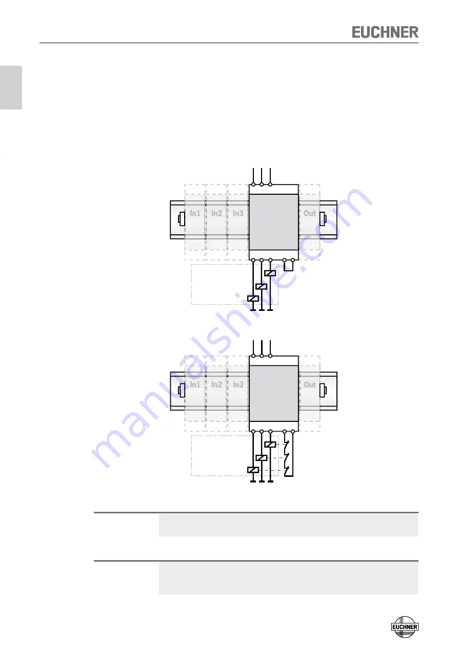
Connecting safety contacts and feedback loop
The base unit has three redundant, error monitored safety contacts that shut down
immediately if one of the safety circuits connected is interrupted or a fault occurs.
To check the switching state on a connected load, the auxiliary contacts on a con-
tactor or relay can be connected to terminals
Y1
and
Y2
to form a feedback loop.
If a feedback loop is not connected, a jumper must be fitted to the terminals
Y1
and
Y2
(see
Figure 9
). The system can be expanded with further safety contacts using
additional output modules. The function of the safety contacts and the feedback
loop for the output modules is the same as for the base unit.
Base
33
23
13
Y2
Y1
24 34
14
+24 V
Subsequent
devices
(e.g. contactors)
Figure 9: Safety contacts connected and jumper on the feedback loop
Base
Subsequent
devices
(e.g. contactors)
33
23
13
Y2
Y1
24 34
14
+24 V
Figure 10: Safety contacts and feedback loop connected
Important!
If you do not connect the feedback loop, the downstream devices will not be
monitored. This situation will effect the safety category of your system.
Caution!
In the event of a fault (e. g. short circuit) in the load circuit, excessively high
currents may flow through the safety contacts. For protection against welding,
each contact must be individually protected with an external fuse.


