Operating Instructions MODULAR SAFETY CONTROL SYSTEM MSC
MSC FIELDBUS MODULES CE-...
4
(Translation of the original operating instructions) 2121341-06-11/20
2. Introduction
The operation of the fieldbus modules in the series MSC is described in this technical data sheet:
CE-PR (PROFIBUS DP-V1), CE-DN (DeviceNet), CE-CO (CANOpen), CE-EC (ETHERCAT), CE-EI (ETHERNET/IP),
CE-EI2 (Ethernet I/O - 2 PORT), CE-PN (PROFINET), CE-MT (Modbus TCP), CE-MR (Modbus RTU), CE-US (USB).
3. Electrical connections
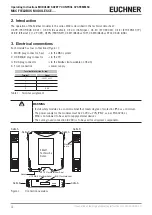
Each module has four connections (Figure 1):
1. MSCB plug connector, 5-pin
to the MSC system
2. USB Mini-B plug connector
to the PC
3. BUS plug connector
to the fieldbus (not available on CE-US)
4. Front connection
power supply
Terminal block (side A – top)
Terminal
Signal
1
24 VDC ± 20%
2
-
3
-
4
GND
Table 1: Terminal assignment
WARNING
Ì
Install safety modules in a control cabinet that meets degree of protection IP54 as a minimum.
Ì
The power supply for the modules must be 24 VDC ± 20% (PELV, as per EN 60204-1).
Ì
MSC is not allowed to be used to supply external devices.
Ì
The same ground connection (0 VDC) is to be used for all system components.
Seite A
Seite B
Etikett
Technische
Daten
Seite A
Seite B
Klemmen-
leiste
Seite B
Seite A
Haken
MSCB Steckverbinder 5-pol.
USB Mini-B-Steckverbinder BUS-Steckverbinder
Figure 1:
Connection overview


