Operating Instructions MODULAR SAFETY CONTROL SYSTEM MSC
MSC FIELDBUS MODULES CE-...
22
(Translation of the original operating instructions) 2121341-06-11/20
7. Example diagnostics
7.1. Example 1
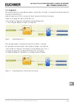
In the example in Figure 7, input 1 (connected to module MSC-CB) is tested using the test signal MSC-CB-Test1.
During the wiring work, 24 VDC is connected to input 1 instead of the test signal MSC-CB-Test1.
Ì
The “I/O index” and “Diagnostic code” fields assume the following values:
1 - 20 to display the diagnosis at input 1 of the MSC-CB module (connection error).
Figure 7:
Example diagnostics 1
7.2. Example 2
NOTICE
The I/O index corresponds to the logical block and not the terminal number on the module MSC-CB.
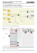
In Figure 8, the two-hand switching element connected to the terminals “Input1” and “Input2” corresponds to I/O index no.
1 and the emergency stop button connected to the terminals “Input3” and “Input4” corresponds to I/O index no. 2.
Figure 8:
Example diagnostics 2


